Download
1 / 4
40 likes | 47 Vues
FLUE GAS FROM GASIFIER. LEGEND. STEAM F.G. CO 2 MEA CO H 2 CH 4. H 2. N 2. N 2. MEA-01. MEA-02. MEA-03. CH 4. CATALYTIC CONVERTER METHANE. LIGNITE. HYDROGEN PRODUCER. CO CONVERTOR. ASH. GAS SCRUBBER 04. CO 2 STRIPPER 05. ST ST. NaHCO 3. PURE MEA 06.

E N D
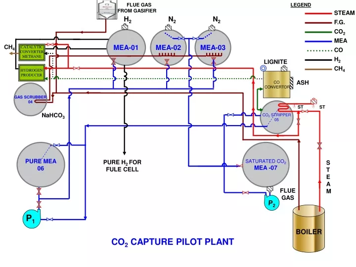
FLUE GAS FROM GASIFIER LEGEND STEAM F.G. CO2 MEA CO H2 CH4 H2 N2 N2 MEA-01 MEA-02 MEA-03 CH4 CATALYTIC CONVERTER METHANE LIGNITE HYDROGEN PRODUCER CO CONVERTOR ASH GAS SCRUBBER 04 CO2 STRIPPER 05 ST ST NaHCO3 PURE MEA 06 SATURATED CO2 MEA -07 STEAM PURE H2 FOR FULE CELL FLUE GAS P2 BOILER P1 CO2 CAPTURE PILOT PLANT
OPERATING PROCEDURE FOR CO2 SEQUESTRATION UNIT. 1. There are three Mono Ethano Amine (MEA) tanks called MEA-1,2,3 and one Saturated , CO2 Rich -MEA tank No.7 and one Pure MEA tank no 6. MEA from pure tank-6 is transferred to MEA -1,2,3. 2. The flue gasses contain Nitrogen and trace impurities like SO2 and NO2,etc and CO2 up to 17- 19%. These come out at an elevated temperature from the Boiler / Gasifier generator and are released first into the Alkali Scrubber No.4 and then into MEA Tank 2 & 3 for stripping the same of CO2 after this the balance N2 gas is vented to the atmosphere. 3. The CO2 rich MEA Solvent is then taken to the stripper and the CO2 is stripped at 120°C by using Steam from the boiler by means of a SS Coil placed in the stripper Tank No.5 via tank No. 7 and using pump.
The Pure CO2 is taken to the CO converter which has burning Lignite Briquettes and once the same is passed, the CO2 converts itself into CO. The lean or purified MEA is taken to the Pure MEA Tank No.6. • The CO is in heated condition and taken to the Hydrogen producer where the Steam is mixed with CO to produce CO2 and H2 and this mixture is sent to MEA-1 tank to strip the same of CO2 and pure Hydrogen is obtained. Once the Hydrogen is produced then the same is taken to the Fuel Cell to produce power or for production of Methane in the Methane converter. • The Methane producer contains a mixed bed catalyst to convert a mixture of CO, H2 and steam into Methane. • The combustion gas analyzer is used to test the quality of the Feed gas to the Boiler or the Generator.
1. Steam Pipe- Seam less steam pipe - 1” Nb (i) Boiler to Stripper - 11.9 m (ii) Stripper to H2 producer - 9.5 m 21.4 m (22 m) 2. MEA line - SS- 304 (1” Nb) (i). Sat tank to stripper - 4.5 m (ii). MEA, 1,2,3 to saturated - 7.5 m (iii). Stripper tank to pure MEA - 13.5 m (iv). Pure MEA to MEA 1,2,3 - 9.5 m (v). Inter connection 1,2,3 - 4.5 m 39.5 m 3. Flue Gas - MS 3” Nb (insulated) (i) Boiler to scriber - 21 m (ii) Gasifier to scriber - 9.5 m 30.5 m (31 m) 4. CO2 & CO - MS 1” Nb (i) CO2 stripper to CO converter - 2 m (ii) CO stripper to H2 & Methane converter - 9.5 m 11.5 m (12 m) 5. Hydrogen MS 1” Nb (i) H2 producer to MEA -1 - 5.5 m (ii) Catalytic converter to CH4 - 4.5 m (iii) Extra piping for Hydrogen - 4.0 m 14.0 m