Download
1 / 55
560 likes | 811 Vues
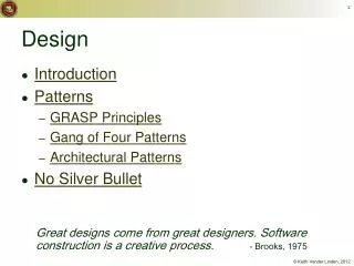
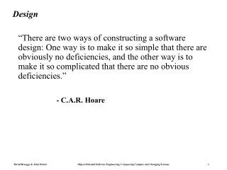
Design. “There are two ways of constructing a software design: One way is to make it so simple that there are obviously no deficiencies, and the other way is to make it so complicated that there are no obvious deficiencies.” - C.A.R. Hoare. Stairs. Stairs. Master. Bedroom. N.

E N D
Design “There are two ways of constructing a software design: One way is to make it so simple that there are obviously no deficiencies, and the other way is to make it so complicated that there are no obvious deficiencies.” - C.A.R. Hoare
Stairs Stairs Master Bedroom N Figure 6-1. Example of iterative floor plan design. Three successive versions show how we minimize walking distance and take advantage of sunlight. Version 1 Version 2 Study Study Dining Bedroom2 Kitchen Kitchen Entrancedoor Entrancedoor Hallway Hallway Bath Master Dining Bath Bedroom2 Bedroom Stairs Entrance door Bath Study Bedroom2 Kitchen Hallway Master Dining Bedroom Version 3
Overview System Design I (chap6_1) 0. Overview of System Design 1. Design Goals 2. Subsystem Decomposition System Design II (chap6_2) 3. Concurrency 4. Hardware/Software Mapping 5. Persistent Data Management 6. Global Resource Handling and Access Control 7. Software Control 8. Boundary Conditions
Figure 6-2. The activities of system design (UML activity diagram).
Why is Design so Difficult? • Analysis: Focuses on the application domain • Design: Focuses on the implementation domain • Design knowledge is a moving target • The reasons for design decisions are changing very rapidly • Halftime knowledge in software engineering: About 3-5 years • What I teach today (specific technology) will be out of date in 3-5 years • Cost of hardware rapidly sinking • “Design window”: • Time in which design decisions have to be made
The Purpose of System Design Problem • Bridging the gap between desired and existing system in a manageable way • Use Divide and Conquer • We model the new system to be developed as a set of subsystems New System Existing System
1. Design Goals Defi nition T rade-of fs 8. Boundary Conditions Initialization T ermination System Design System Design Failure 2. System Decomposition Layers/Partitions Coherence/Coupling 7. Software Control Monolithic Event-Driven Threads Conc. Processes 3. Concurrency 6. Global 4. Hardware/ Identification of Threads 5. Data Resource Handling Softwar e Management Mapping Access control Security Persistent Objects Special purpose Files Buy or Build Trade-off Databases Allocation Data structure Connectivity
How to use the results from the Requirements Analysis for System Design • Nonfunctional requirements => • Activity 1: Design Goals Definition • Use Case model => • Activity 2: System decomposition (Selection of subsystems based on functional requirements, coherence, and coupling) • Object model => • Activity 4: Hardware/software mapping • Activity 5: Persistent data management • Dynamic model => • Activity 3: Concurrency • Activity 6: Global resource handling • Activity 7: Software control • Activity 8: Boundary conditions
Section 1. Design Goals • Good documentation • Well-defined interfaces • User-friendliness • Reuse of components • Rapid development • Minimum # of errors • Readability • Ease of learning • Ease of remembering • Ease of use • Increased productivity • Low-cost • Flexibility • Reliability • Modifiability • Maintainability • Understandability • Adaptability • Reusability • Efficiency • Portability • Traceability of requirements • Fault tolerance • Backward-compatibility • Cost-effectiveness • Robustness • High-performance
Developer/ Maintainer Relationship Between Design Goals End User Functionality User-friendliness Ease of Use Ease of learning Fault tolerant Robustness Low cost Increased Productivity Backward-Compatibility Traceability of requirements Rapid development Flexibility Runtime Efficiency Reliability Portability Good Documentation Client (Customer, Sponsor) Minimum # of errors Modifiability, Readability Reusability, Adaptability Well-defined interfaces
Typical Design Trade-offs • Functionality vs. Usability • Cost vs. Robustness • Efficiency vs. Portability • Rapid development vs. Functionality • Cost vs. Reusability • Backward Compatibility vs. Readability
Nonfunctional Requirements give a clue for the use of Design Patterns • Read the problem statement again • Use textual clues (similar to Abbot’s technique in Analysis) to identify design patterns • Text: “manufacturer independent”, “device independent”, “must support a family of products” • Abstract Factory Pattern • Text: “must interface with an existing object” • Adapter Pattern • Text: “must deal with the interface to several systems, some of them to be developed in the future”, “ an early prototype must be demonstrated” • Bridge Pattern
Textual Clues in Nonfunctional Requirements • Text: “complex structure”, “must have variable depth and width” • Composite Pattern • Text: “must interface to an set of existing objects” • Façade Pattern • Text: “must be location transparent” • Proxy Pattern • Text: “must be extensible”, “must be scalable” • Observer Pattern • Text: “must provide a policy independent from the mechanism” • Strategy Pattern
Section 2. System Decomposition • Subsystem (UML: Package) • Collection of classes, associations, operations, events and constraints that are interrelated • Seed for subsystems: UML Objects and Classes. • Service: • Group of operations provided by the subsystem • Seed for services: Subsystem use cases • Service is specified by Subsystem interface: • Specifies interaction and information flow from/to subsystem boundaries, but not inside the subsystem. • Should be well-defined and small. • Often called API: Application programmer’s interface, but this term should used during implementation, not during System Design
Services and Subsystem Interfaces • Service: A set of related operations that share a common purpose • Notification subsystem service: • LookupChannel() • SubscribeToChannel() • SendNotice() • UnscubscribeFromChannel() • Services are defined in System Design • Subsystem Interface: Set of fully typed related operations. Also called application programmer interface (API) • Subsystem Interfaces are defined in Object Design
DispatcherInterface FieldOfficerInterface Figure 6-4. Subsystem decomposition for an accident management system (UML class diagram, collapsed view). Subsystems are shown as UML packages. Dashed arrows indicate dependencies between subsystems. Notification IncidentManagement
Choosing Subsystems • Criteria for subsystem selection: Most of the interaction should be within subsystems, rather than across subsystem boundaries (High coherence). • Does one subsystem always call the other for the service? • Which of the subsystems call each other for service? • Primary Question: • What kind of service is provided by the subsystems (subsystem interface)? • Secondary Question: • Can the subsystems be hierarchically ordered (layers)? • What kind of model is good for describing layers and partitions?
Definition: Subsystem Interface Object • A Subsystem Interface Object provides a service • This is the set of public methods provided by the subsystem • The Subsystem interface describes all the methods of the subsystem interface object • Use a Facade pattern for the subsystem interface object
RouteAssistant PlanningService Trip Location Direction Destination Crossing Segment Figure 6-28. Analysis model for the MyTrip route planning and execution.
PlanningSubsystem RoutingSubsystem RouteAssistant PlanningService Trip Location Direction Destination Crossing Segment Figure 6-29. Initial subsystem decomposition for MyTrip (UML class diagram).
CommunicationSubsystem Message Connection Figure 6-32. Revised design model for MyTrip (UML Class diagram, associations omitted for clarity). PlanningSubsystem RoutingSubsystem RouteAssistant PlanningService Trip Location Destination TripProxy Direction Crossing SegmentProxy Segment
RoutingSubsystem CommunicationSubsystem TripFileStoreSubsystem Figure 6-35. Subsystem decomposition of MyTrip after deciding on the issue of data stores (UML class diagram, packages collapsed for clarity). PlanningSubsystem MapDBStoreSubsystem
Coupling and Coherence • Goal: Reduction of complexity • Coherence measures the dependence among classes • High coherence: The classes in the subsystem perform similar tasks and are related to each other (via associations) • Low coherence: Lots of misc and aux objects, no associations • Coupling measures dependencies between subsystems • High coupling: Modifications to one subsystem will have high impact on the other subsystem (change of model, massive recompilation, etc.) • Subsystems should have as maximum coherence and minimum coupling as possible: • How can we achieve loose coupling? • Which subsystems are highly coupled?
Binary tree representation Figure 6-5. Example of coupling reduction (UML object diagram and Java declarations). This figure shows a parse tree for the expression “a + b + c”. The left column shows the interface of the OpNode class with sharing through attributes. The right column shows the interface of OpNode with sharing through operations. Figure 6-6 shows the changes for each case when a linked list is selected instead. add1:OpNode a:ArgNode add2:OpNode b:ArgNode c:ArgNode Sharing through attributes class OpNode { ArgNode left; ArgNode right; String name; } class ArgNode { String name; } Sharing through operations class OpNode { Enumeration getArguments(); String getName(); } class ArgNode { String getName(); }
add:OpNode a:ArgNode b:ArgNode c:ArgNode Figure 6-6. Example of coupling reduction (UML object diagram and Java declarations). This figure shows the impact of changing the parse tree representation of Figure 6-5 to a linked list. In the left column, with sharing through attributes, four attributes need to change (changes indicated in italics). In the right column, with sharing through operations, the interface remains unchanged. Linked list representation Sharing through attributes class OpNode { ArgNode first; ArgNode left; ArgNode right; String name; } class ArgNode { String name; ArgNode next; } Sharing through operations class OpNode { Enumeration getArguments(); String getName(); } class ArgNode { String getName(); }
Figure 6-7. Decision tracking system (UML class diagram). The DecisionSubsystem has a low coherence: The classes Criterion, Alternative, and DesignProblem have no relationships with Subtask, ActionItem, and Task.
RationaleSubsystem assesses Criterion Alternative * * * solvableBy based-on DesignProblem resolvedBy Decision PlanningSubsystem implementedBy SubTask * subtasks ActionItem Task Figure 6-8. Alternative subsystem decomposition for the decisiontracking system of Figure 6-7 (UML class diagram). The coherence of the RationaleSubsystem and the PlanningSubsystem is higher than the coherence of the original DecisionSubsystem. Note also that we also reduced the complexity by decomposing the system into smaller subsystems.
Partitions and Layers A large system is usually decomposed into subsystems using both, layers and partitions. • Partitions vertically divide a system into several independent (or weakly-coupled) subsystems that provide services on the same level of abstraction. • A layer is a subsystem that provides services to a higher level of abstraction • A layer can only depend on lower layers • A layer has no knowledge of higher layers
Properties of Layered Systems • Layered systems are hierarchical. They are desirable because hierarchy reduces complexity. • Closed architectures are more portable. • Open architectures are more efficient. • If a subsystem is a layer, it is often called a virtual machine. • Layered systems often have a chicken-and egg problem
Layer 1 Layer 2 Layer 3 Subsystem Decomposition into Layers • Subsystem Decomposition Heuristics: • No more than 7+/-2 subsystems • More subsystems increase coherence but also complexity (more services) • No more than 5+/-2 layers
Layer and Partition Relationships between Subsystems • Layer relationship • Layer A “Calls” Layer B (runtime) • Layer A “Depends on” Layer B (“make” dependency, compile time) • Partition relationship • The subsystem have mutual but not deep knowledge about each other • Partition A “Calls” partition B and partition B “Calls” partition A
Figure 6-12. An example of open architecture: the OSF/Motif library (UML class diagram, packages collapsed). Xlib provides low-level drawing facilities. Xt provides basic user interface widget management. Motif provides a large number of sophisticated widgets. The Application can access each of these layers independently. Application Motif Xt Xlib
Application Presentation Format Session Connection Level of abstraction Transport Message Network Packet DataLink Frame Physical Bit Figure 6-10. An example of closed architecture: the OSI model (UML class diagram). The OSI model decomposes network services into seven layers, each responsible for a different level of abstraction.
Application Object Presentation CORBA Session Transport Socket TCP/IP Network DataLink Physical Ethernet Wire Figure 6-11. An example of closed architecture (UML class diagram). CORBA enables the access of objects implemented in different languages on different hosts. CORBA effectively implements the Presentation and Session layers of the OSI stack.
Virtual Machine • A virtual machine is an abstraction that provides a set of attributes and operations. • A virtual machine is a subsystem connected to higher and lower level virtual machines by "provides services for" associations. • Virtual machines can implement two types of software architecture: closed and open architectures.
Virtual Machine (Dijkstra, 1965) • A system should be developed by an ordered set of virtual machines, each built in terms of the ones below it. Problem VM1 C1 C1 C1 attr attr attr opr opr opr C1 C1 VM2 attr attr opr opr C1 VM3 C1 attr attr opr opr C1 VM4 attr opr Existing System
C1 C1 C1 C1 C1 C1 C1 C1 C1 VM1 attr attr attr attr attr attr attr attr attr op op op op op op op op op VM2 VM3 VM4 Closed Architecture (Opaque Layering) • A virtual machine can only call operations from the layer below • Design goal: High maintainability
C1 C1 C1 C1 C1 C1 C1 C1 C1 attr attr attr attr attr attr attr attr attr op op op op op op op op op Open Architecture (Transparent Layering) • A virtual machine can call operations from any layers below • Design goal: Runtime efficiency VM1 VM2 VM3 VM4
Software Architectures • Subsystem decomposition • Identification of subsystems, services, and their relationship to each other. • Specification of the system decomposition is critical. • Patterns for software architecture • Repository Architecture • Client/Server Architecture • Peer-To-Peer Architecture • Model/View/Controller • Pipes and Filters Architecture
Repository Subsystem createData() setData() getData() searchData() Repository Architecture • Subsystems access and modify data from a single data structure • Subsystems are loosely coupled (interact only through the repository) • Control flow is dictated by central repository (triggers) or by the subsystems (locks, synchronization primitives)
SemanticAnalyzer Repository SymbolTable ParseTree SourceLevelDebugger Examples of Repository Architecture Compiler • Hearsay II speech understanding system (“Blackboard architecture”) • Database Management Systems • Modern Compilers SyntacticAnalyzer Optimizer CodeGenerator LexicalAnalyzer SyntacticEditor
Client/Server Architecture • One or many servers provides services to instances of subsystems, called clients. • Client calls on the server, which performs some service and returns the result • Client knows the interface of the server (its service) • Server does not need to know the interface of the client • Response in general immediately • Users interact only with the client
Client/Server Architecture • Often used in database systems: • Front-end: User application (client) • Back end: Database access and manipulation (server) • Functions performed by client: • Customized user interface • Front-end processing of data • Initiation of server remote procedure calls • Access to database server across the network • Functions performed by the database server: • Centralized data management • Data integrity and database consistency • Database security • Concurrent operations (multiple user access) • Centralized processing (for example archiving)
Figure 6-18. Client/server architecture (UML class diagram). Clients request services from one or more Servers. The Server has no knowledge of the Client. The client/server architecture is a generalization of the repository architecture. Server * * Client requester provider service1() service2() … serviceN()
Figure 6-19. The World Wide Web as an instance of the client/server architecture (UML object diagram). netscape:WebBrowser www12.in.tum.de:WebServer iexplorer:WebBrowser lynx:WebBrowser www.cs.cmu.edu:WebServer mosaic:WebBrowser
Design Goals for Client/Server Systems • Portability • Server can be installed on a variety of machines and operating systems and functions in a variety of networking environments • Transparency • The server might itself be distributed (why?), but should provide a single "logical" service to the user • Performance • Client should be customized for interactive display-intensive tasks • Server should provide CPU-intensive operations • Scalability • Server has spare capacity to handle larger number of clients • Flexibility • Should be usable for a variety of user interfaces • Reliability • System should survive individual node and/or communication link problems
Problems with Client/Server Architectures • Layered systems do not provide peer-to-peer communication • Peer-to-peer communication is often needed • Example: Database receives queries from application but also sends notifications to application when data have changed
Peer-to-Peer Architecture • Generalization of Client/Server Architecture • Clients can be servers and servers can be clients • More difficult because of possibility of deadlocks
initiator Controller 1 repository * Model 1 notifier subscriber View * Model/View/Controller • Subsystems are classified into 3 different types • Model subsystem: Responsible for application domain knowledge • View subsystem: Responsible for displaying application domain objects to the user • Controller subsystem: Responsible for sequence of interactions with the user and notifying views of changes in the model. • MVC is a special case of a repository architecture: • Model subsystem implements the central datastructure, the Controller subsystem explicitly dictate the control flow