Download
1 / 64
640 likes | 778 Vues
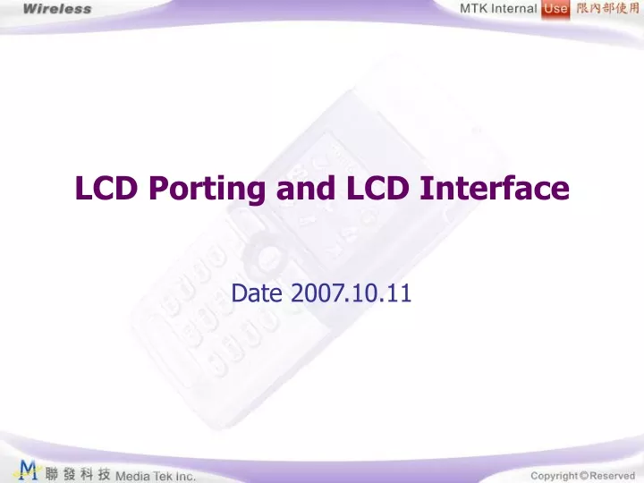
LCD Porting and LCD Interface. Date 2007.10.11. Agenda. LCD 与 Baseband 的连接 LCD porting LCD interface. LCD block diagram ( 1/2 ). LCD pin description. 1. input parts 2. output parts 3. input/output parts 4. power parts 5. test pins and others 液晶显示的原理是液晶在不同电压的作用下会呈现出不同的光特性。

E N D
LCD Porting and LCD Interface Date 2007.10.11
Agenda • LCD与Baseband的连接 • LCD porting • LCD interface
LCD pin description • 1. input parts • 2. output parts • 3. input/output parts • 4. power parts • 5. test pins and others • 液晶显示的原理是液晶在不同电压的作用下会呈现出不同的光特性。 • LCD真彩显示使用TFT型LCD,主动点阵显示,需要采用源极驱动器(source driver)和栅极驱动器(gate driver)去控制LCD场效应晶体管FET的源极与栅极。源极驱动器接收显示数据驱动LCD列显示,也称为数据驱动器(data driver)栅极驱动器控制逐行扫描。
Baseband的LCD接法(1/5) • BB 的LCM接法主要有NFI,EMI 和serial 三种接法: • 1. 并行接法 • a. 专用NFI(nand flash interface),支持8080总线接口。 • 8 bit: NLD0~NLD7 • 9 bit: NLD0~NLD8 • 16 bit: NLD0~NLD15 • 18 bit: NLD0~NLD17
Baseband的LCD接法(2/5) • b. 复用EMI,支持8080总线接口。
Baseband的LCD接法(3/5) • 2. 串行接法 • 串行接口完成并行数据到串行数据的转换过程,支持8bit和9bit的传输方式: • a.8bit串口需要 以下4根线来完成数据和命令的传输:LSCE#, LSDA,LSCK 和LSA0 • b.9bit串口需要以下3根线来完成数据和命令的传输: LSCE#, LSDA和LSCK
Baseband的LCD接法(5/5) • 虽然这三种接口方式都可以选用,但从性能的角度考虑推荐使用NFI,它有如下优点: • 有专用LCD controller 实现硬件加速 • 不用和memory复用EMI总线,从而Flash/SRAM 和LCD 都会有比较好的表现。
LCD与Baseband的连接 • LCD porting • LCD interface
前期准备 • 首先期望能有如下文档的源代码: • Lcd_if.c • lcd.c • lcd_hw.h • lcd_sw.h • lcd_sw_inc.h • lcd_sw_rnd.h • custom_hw_default.c
custom_hw_default.c • Open \custom\drv\misc_drv\[project]\custom_hw_default.c Contrast level
Lcd_if.h(2/3) • This function is to initialize MainLCD and SubLCD pointer of LCM. This function must be implemented for all LCMs. And all of the function pointer for LCD_Funs structure has to be assigned and implemented even it is as empty function.
Lcd_if.h(3/3) • 在lcd_if.h中还定义了: • LCD interface中寄存器地址映射 • 为操作寄存器中的位的bit mapping • Macros for registers • definition of LCM data outptu format • MAIN_LCD_CMD_ADDR, MAIN_LCD_DATA_ADDR • SUB_LCD_CMD_ADDR, SUB_LCD_DATA_ADDR
LCD driver porting procedure • Step1:HW & build environment confirmation • 确定硬件没有问题。 • 准备好Code Base。最好与新屏类似的,比如新屏是双彩的屏,如果Code Base本就是双彩的,可能会免去不少麻烦。 • Down入一个类似的Bin后,期望能有背光亮起来。否则先调背光。
Step 2: Study LCD spec & vender’s init code 当确认(或基本确认)外部电路没有问题后,接下来一般可以先看LCD spec,同时对照着spec看供应商提供的init 程序,对当前芯片的操作模式有所了解。参照spec进行正确的连接。
Step3:Define the color & panel option in [project name]_GPRS.mak • COM_DEFS_FOR_XXXX_LCM = • COLOR_LCD MAIN LCD • COLOR_SUBLCD SUB LCD • DUAL_LCD TWO LCDS
Step 4: Declare DUAL_LCD option or not • 在**.mak里定义。 • 如果不是双屏,DUAL_LCD要拿掉,否则必须予以定义 Step5: Turn on the LCD_CMD_DMA_MODE option or not in LCD_SW.H #define LCD_CMD_DMA_MODE The LCD_CMD_DMA_MODE is the compiler option for LCD module command. If it is defined, the LCM command will be sent by LCD interface DMA. If the LCM with slower response time, the compiler option should not be defined to make sure the LCM can receive commands correctly.
Step 6: 在lcd_sw.h中确定Ctrl和Data的地址线,以及Command和Data的读写方式 These definitions declare the main/sub LCD command and data address port for hardware LCD interface to send command and data. These addresses should be defined according to the hardware configuration.
Step 7: Define main/sub LCD output format #define MAIN_LCD_OUTPUT_FORMAT LCM_8BIT_16_BPP_RGB565_1 #define SUB_LCD_OUTPUT_FORMAT LCM_8BIT_12_BPP_RGB444_1
Step8:Implement LCD_CtrlWrite_HD66773R(_data) LCD_DataWrite_HD66773R(_data) in lcd_sw.h
while (LCD_IS_RUNNING); • #define LCD_IS_RUNNING (REG_LCD_STA & LCD_STATUS_RUN_BIT) • #define REG_LCD_STA *((volatile unsigned short *) (LCD_base+0x0000)) • #define LCD_STATUS_RUN_BIT 0x0001
/* disable lcd frame transfer complete interrupt control */ • DISABLE_LCD_TRANSFER_COMPLETE_INT;\ • DISABLE_ALL_LCD_LAYER_WINDOW;\ • SET_LCD_ROI_CTRL_NUMBER_OF_CMD(n);\ • ENABLE_LCD_ROI_CTRL_CMD_FIRST;\ • #define DISABLE_ALL_LCD_LAYER_WINDOW REG_LCD_ROI_CTRL &= ~LCD_ROI_CTRL_LAYER_MASK; • #define SET_LCD_ROI_CTRL_NUMBER_OF_CMD(n) REG_LCD_ROI_CTRL &= ~LCD_ROI_CTRL_CMD_NUMBER_MASK;\ REG_LCD_ROI_CTRL |= ((n-1)<<7); • #define ENABLE_LCD_ROI_CTRL_CMD_FIRST REG_LCD_ROI_CTRL |= LCD_ROI_CTRL_CMD_ENABLE_BIT; • #define LCD_ROI_CTRL_LAYER_MASK 0xF0000000 • #define LCD_ROI_CTRL_CMD_NUMBER_MASK 0x00001F00 • #define LCD_ROI_CTRL_CMD_ENABLE_BIT 0x00008000
DMA model CtrlWrite: Non DMA: LCD_HX8306A_CTRL_ADDR LCD_HX8306A_DATA_ADDR 把LPA0拉高,拉低。
Step11:Configure void init_lcd_interface(void) • This function is used to configure the read/write timing of LCM. They should include the following items. • CS to WR setup time by use the macro SET_LCD_PARALLEL_CE2WR_SETUP_TIME(n). n<=3 • CS to WR hold time by use the macro SET_LCD_PARALLEL_CE2WR_HOLD_TIME(n), n<=3 • CS to RD setup time by use the macro SET_LCD_PARALLEL_CE2RD_SETUP_TIME(n), n<=3 • Data write wait state period by use the macro SET_LCD_PARALLEL_WRITE_WAIT_STATE(n), n<=31 • Data read latency period by use the macro SET_LCD_PARALLEL_READ_LATENCY_TIME(n), n<=31 • Data read/write interval between two data read/write can be set by use macro SET_LCD_ROI_CTRL_CMD_LATENCY(n), n<=1023
Step12:Implement LCD_Init_HD66773R() LCD_BlockWrite_HD66773R() First, then you can see something on the LCD BlockWriteis to move data from frame buffer to LCD module. For MT6205B, the frame buffer address should be get by calling get_lcd_frame_buffer_address() function that declares in lcd_if.c. For MT6218B and MT6219, if color LCM is used, the frame buffer address has been assigned in the LCD interface, LCM driver does not have to know the address of frame buffer. If mono LCM is provided in MT6218B/MT6219, LCD driver also need to get the frame buffer address by calling get_lcd_frame_buffer_address() function
LCD与Baseband的连接 • LCD porting • LCD interface
LCD controller(1/2) • 显示屏所显示的一幅完整画面就是一个帧(Frame),其整个显示区域,在系统内会有一段存储空间与之对应,通过改变该存储空间的内容,从而改变显示屏的内容,该存储空间被称为Frame Buffer。显示屏上的每一点都必然与Frame Buffer里的某一位置对应。而计算机显示的颜色是通过RGB值来表示的,因此如果要在屏幕某一点显示某种颜色,则必须给出相应的RGB值。Frame Buffer就是用来存放整个显示的编码和像点值的外部存储器区域。帧缓冲器的每一个字节对应着LCD中的一个像素。 • Frame Buffer和LCD显示屏之间的数据传输很频繁,完全由CPU通过程序直接驱动显然不合适。因此,为减轻CPU的负担,在Frame Buffer与显示屏之间还需要一个中间件,该中间件负责从Frame Buffer里提取数据,进行处理,并传输到显示屏上。
LCD controller(2/2) • LCD控制器的功能是显示驱动信号,进而驱动LCD显示器。在驱动LCD设计的过程中首要的是配置LCD控制器。在配置LCD控制器中最重要的一步则是帧缓冲区的指定。用户所要显示的内容皆是从缓冲区中读出,从而显示到屏幕上。帧缓冲区的大小由屏幕的分辨率和显示色彩数决定。 • LCD控制器用来传输图像数据并产生相应的控制信号,MT6226’s lcd controller’s features:
the LCD interface supports multi-layers frame buffer output to LCM simultaneously after overlaying the data of the specified layers. With the ability to overlay multiple layers of data, the LCD module can apply an opacity effect. • 可以通过lcd_if.c中的 • kal_uint32 get_lcd_frame_buffer_address(void)来取得每个frame buffer的地址。
Lcd interface • The LCD interface provides a standard API for the upper layer AP to develop its image display. The LCD interface supports multi-layer frame buffer output to LCM simultaneously after overlaying the data of the specified layers.
LCD_IDLE_STATE: At the beginning, LCD operation stops at LCD_IDLE_STATE. • LCD_INITIAL_STATE: The LCD is being initialized. When LCD initialization is complete, the state transits to LCD_STANDBY_STATE that is the temporary state of LCD state machines. • LCD_STANDBY_STATE: • LCD_SW_UPDATE_STATE: The LCD is busy with a software-triggered frame update process that is in progress. The state moves back to LCD_STANDBY_STATE when the data transfer is complete. The task that triggers the lcd software update is blocked until the data transfer is complete. After the frame is transferred complete, the state moves back to LCD_STANDBY_STATE. • LCD_SLEEP_STATE: The LCD is in sleep mode, all backlights and LCD screen are turned off. The state moves back to LCD_STANDBY_STATE when lcd_sleep_out() function is called.
LCD_MEM_UPDATE_STATE: This state is a temporary state. LCD operation returns to its source state after the data transfers completely. • LCD_CAMERA_ACTIVE_STATE: In this state, the external camera module is activated and the LCD update procedure is performed by the external camera module. The state changes to LCD_CAMERA_UPDATE_STATE after the external camera starts image preview. • LCD_CAMERA_UPDATE_STATE: In this state, the control of LCM updated transfers to the external camera driver. • LCD_CAMERA_CMD_QUEUE_STATE • LCD_HW_UPDATE_STATE • LCD_DC_UPDATE_STATE • LCD_HW_CMD_QUEUE_STATE • LCD_DC_CMD_QUEUE_STATE • LCD_HW_UPDATE_SLEEP_STATE • LCD_DC_UPDATE_SLEEP_STATE • LCD_JPEG_VIDEO_UPDATE_STATE • LCD_JPEG_VIDEO_CMD_QUEUE_STATE
Lcd_lcm_if.c • This function implements LCM interface adaptation layer