Download
1 / 1
10 likes | 129 Vues
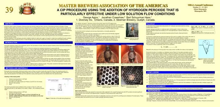
MASTER BREWERS ASSOCIATION OF THE AMERICAS. MBAA Annual Conference October 13 – 15, 2011 Hilton Minneapolis Minneapolis, MN. 39. A CIP PROCEDURE USING THE ADDITION OF HYDROGEN PEROXIDE THAT IS PARTICULARLY EFFECTIVE UNDER LOW SOLUTION FLOW CONDITIONS.

E N D
MASTER BREWERS ASSOCIATION OF THE AMERICAS MBAA Annual Conference October 13 – 15, 2011Hilton MinneapolisMinneapolis, MN 39 A CIP PROCEDURE USING THE ADDITION OF HYDROGEN PEROXIDE THAT IS PARTICULARLY EFFECTIVE UNDER LOW SOLUTION FLOW CONDITIONS George Agius,1 Jonathan Crawshaw,2 Bart Schuurman Hess,1 1. Diversey Inc. Ontario, Canada, 2. Sleeman Brewery, Guelph, Canada. The addition rate was 0.7 liters per minute to the suction side of the CIP supply pump. As a starting point the volume of hydrogen peroxide required can be calculated as 1% of the volume of the CIP tank capacity. The rate of dosing is determined by dividing the volume by the circulation time in step 3. This is important since the addition of too much hydrogen peroxide to the CIP solution would release a large quantity of oxygen and cause cavitation of the CIP supply pump [5]. ABSTRACT Theoretical On the basis of its standard electrode potential, Eo, hydrogen peroxide should be a strong oxidizing agent (Figure 7). H2O2 + 2H+ + 2e- 2H2O Eo = 1.76V Figure 7Half reaction of hydrogen peroxide to water During the clean in place of brewery equipment there are several instances where the flow of the cleaning solution is limited. In these situations there is little mechanical action imparted by the circulating cleaning solution to help remove soils. In some extreme cases the flow could be so limited that some areas of the surface may not be wetted by the cleaning solution. Increasing the flow by increasing the size of CIP pumps is often not practical and the remaining combination of chemical action, time and temperature may not be sufficient to completely remove all soils from the surface. In critical areas the remaining soils may become a source of microbiological infection. The addition of hydrogen peroxide to the circulating CIP solution has been effectively employed over a number of equipment surfaces to achieve consistent cleaning including the lautertun, brew kettle, whirlpool, wort loop, centrifuge and plate heat exchangers. The improved cleaning of the surfaces has been verified by visual inspection and the cleaning performance has remained consistent over a period of several months. The decomposition of the hydrogen peroxide in alkaline media into water and oxygen is thought to create micro-bubbling through nucleation, that generate surface mechanical action to help dislodge the soils and also increase the surface contact area of the cleaning solution. Actually, hydrogen peroxide is a relatively weak oxidizing agent. It does oxidize some specific substrates slowly and unaided, but for most applications it requires activation by catalysts [3]. In basic solutions hydrogen peroxide decomposes quickly through a disproportionation reaction (Figure 8) For the initial trial the hydrogen peroxide was dispensed by a manually operated air diaphragm pump. Subsequently, the process was fully automated using a piston pump automatically triggered by the Clean In Place PLC controller. See Figure 1. This procedure where hydrogen peroxide is added to the caustic solution in step 3 of the CIP was subsequently extended to the CIP of the Lautertun, the plate and frame wort cooler and the centrifuge. All of these three pieces of equipment can have heavy soil deposits and limited CIP solution flow speed. It is also not cost effective to increase flow to the desired level by changing or modifying pumps. 2H2O2 2H2O + O2 Figure 8Decomposition of hydrogen peroxide It is therefore unlikely that the enhanced cleaning is the result of oxidation of the soils by the action of hydrogen peroxide and most likely has more to do with the controlled release of oxygen. The release of oxygen by the decomposition of hydrogen peroxide would super saturate the cleaning solution with oxygen. The excess oxygen is released from the solution by a process of heterogeneous nucleation. The actual soil on the surface would provide suitable crevices which will act as nucleating points to help start, form and release bubbles of oxygen over the surface. The pressure inside a bubble Pb is given by the expression Pb - P = 2S/R ………………. (1) Where P is the pressure of the liquid, S is the surface tension and R is the radius of the bubble [4]. During the formation of a bubble in an idealized crevice (Figure 9), the radius decreases and the pressure increases as the bubble increases in size from the bottom of the crevice to the opening (equation 1). The pressure reaches a maximum when the radius of the bubble is the smallest Rc, and equal to that of the opening of the crevice. The pressure will then reduce as the bubble gets larger and eventually detaches from the surface. The rise and fall of the pressure at the soil surface creates turbulence and mechanical action to help dislodge the soils. Assuming a crevice opening with a radius of the order of 10-5 m to 10-6 m and surface tension of 0.07 N/m then the pressure as calculated by equation 1 is of the order of 1/10 bar to 1 bar. The combined effect of the chemical reaction of the caustic with the soils, and the mechanical disturbance caused by several bubbles forming near to each other, will help to remove soils. It can be surmised that the mechanical disturbance is created in the boundary layer, (a layer of static liquid very close to the surface). Aside from the mechanical action on the soil, the disturbance in the boundary layer brings in fresh solution from the solution bulk to the surface, overcoming normal diffusion processes. Figure 2Picture of Peroxide dosing Equipment R3 INTRODUCTION RESULTS AND DISCUSSION Rc During the cleaning in place of the equipment used for the manufacture of beer, there are several situations where the solution will flow from a small to a large cross-sectional area. The flow in pipes should have a velocity of 5 ft /s (1.5m/s) to achieve the necessary turbulence to remove soils [2]. For example, the solution can flow from a 50mm (2 “) line to a plate heat exchanger where the area increases and the flow speed of the solution over the plates drops dramatically. As a result of this drop in solution flow speed, there is little turbulence to provide sufficient mechanical action to remove adherent soils. There is also the possibility that the solution flow will be uneven over the surface with some areas getting more flow than others, as the solution finds the least resistant path. Under these circumstances the cleaning results will not be uniform. Increasing the flow and turbulence may require changing pumps or modifying the CIP equipment. Increasing the pressure to increase the CIP solution flow could increase the pressure in the lines and the possibility of exceeding the burst tolerance of the sight glasses – a safety issue. This raises the question whether it would be possible to add a chemical during the CIP that can create natural agitation at the soil surface. One way to achieve this is to add a material that can break down to release a harmless gas. As the gas saturates the solution it can form gas bubbles on the surface, using surface defects as nucleating points for the release of the gas. The mechanical agitation created by the release of bubbles would aid in the removal of the soil. Hydrogen peroxide is known to break down rapidly in alkaline solution releasing oxygen. This poster reviews the field experimental results obtained from the addition of hydrogen peroxide during the cleaning of equipment. Kettle Cleaning: Using the new CIP procedure immediate improvements were observed in the total removal of soils from the kettle walls and the difficult to clean calandria tubes. Figures 3 and 4 compare the effect of cleaning using traditional procedure with the modified Hydrogen Peroxide procedure R2 R1 Figure 9Variation of the bubble radius as the bubble grows and emerges from an idealized cavity Figures 6 show the inside of heat exchange tubes of the calandria after using the hydrogen peroxide procedure. Note the absence of any soils after cleaning. This can be compared to Figure 5, showing some deposits remaining after on the tubes after cleaning with caustic only. The improved removal of soils using the new procedure enabled the plant to reduce the need for cleaning to every 4th brew instead of every 3rd brew. It also eliminated the need to remove the accumulation of hard resin soils by hydroblasting from 4 times to 2 times per year. The kettle has subsequently been changed to a more modern design, but the new kettle continues to be cleaned with the new hydrogen peroxide procedure. Figure 4 Kettle after caustic/peroxide wash Figure 3 Kettle after traditional wash METHODS AND MATERIALS Previously, the brewing kettle cleaning procedure used a 3.5%w/v as sodium Hydroxide (Liquid Bril Tak) for the cleaning solution [1] . The CIP solutions were all sprayed via spray balls at the top of the kettle to reach the sidewalls and outside calandria walls. Additional spray balls are placed at the inside top of the calandria to spray cleaning solution that dribbles down the calandria tubes. CONCLUSIONS • The modified CIP procedure employing hydrogen peroxide provides an effective cleaning solution for equipment where the flow speed of the solution is not sufficiently high to give suitable mechanical action. • The improved cleaning action arising from the use of the procedure reduces the down time required for cleaning, thereby presenting an opportunity for enhanced productivity. • The procedure can be implemented simply with the use of dosing equipment to add the hydrogen peroxide and does not require any other capital intensive modifications to the CIP equipment. • The mechanism for the success of this method is believed to result from the breakdown of hydrogen peroxide to release oxygen and subsequent bubble formation on the soiled surface. Cleaning of the brewing kettle CIP supply pump • Prepare cleaning solution in CIP tank • Pre rinse for 300 seconds • Circulate a hot caustic solution at 3.5%w/v [1] at 80oC for 40 minutes • Rinse for 300 seconds • Drain CIP Controller Signal Figure 6 Clean calandria tubes after caustic/peroxide wash Figure 5 Calandria tubes with deposits after caustic only wash ACKNOWLEDGEMENTS The cleaning procedure was modified so that a solution of Triax lll, a 35% w/w hydrogen peroxide [1], was added to the caustic in Step 3. The modified procedure reads Thanks to Doug Funnell, Engineering Project Manager, Diversey Inc., for the design and drawing of the dosing system. 35% H2O2 REFERENCES Wort Cooler Cleaning When the plate wort cooler was opened for examination after subjected to the caustic/hydrogen peroxide CIP procedure showed significant improvements in the removal of soil deposits when compared to the procedure with caustic alone . Centrifuge Following cleaning with caustic alone soils were not adequately removed on the wall of the centrifuge and underside of the disk stacks. These soils were easily removed with the use of caustic/hydrogen peroxide procedure. • Prepare cleaning solution in CIP tank • Pre rinse for 300 seconds • Circulate a hot caustic solution at 3.5%w/v [2] at 80oC for 40 minutes, adding Hydrogen Peroxide over the duration of this step • Rinse for 300 seconds • Drain [1] TRIAX lll and LIQUID BRILTAK purchased from Diversey Inc. [2] Timperley, D. (1981). The effect of Reynolds number and mean velocity of flow on the clean-in-place of Pipelines. In: Proceedings of Fundamentals and Applications of Surface Phenomena Associated with Fouling and Cleaning in Food Processing. Pp402-412. R.Hallstrom, D.B. Lund, and C. Tragardth, eds. University of Lund, Tylosand, Sweden [3] Jones Graig W., Applications of Hydrogen peroxide and derivatives, Chap 2, pp 37, The Royal Society of Chemistry 1999 [4] Brennan C. E., Cavitation and Bubble Dynamics, chp 1, Section 1.10, Oxford University Press(1995) [5] Holger Theyssen, Diversey Senior Director Global RD&E, Food and Beverage Solutions, Mannhein, Germany, Personal Communication Figure 1 Schematic of Peroxide dosing Equipment. Po