Download
1 / 25
270 likes | 437 Vues
Resistivity method without groundings. B.G. Sapozhnikov Institute of Environmental Geology of the Russian Academy of Sciences, St. Petersburg Division. Here is the list of key points of the report:. Is there an electric field in the air at works by a resistivity method?

E N D
Resistivity methodwithout groundings B.G. Sapozhnikov Institute of Environmental Geology of the Russian Academy of Sciences, St. Petersburg Division
Here is the list of key points of the report: Is there an electric field in the air at works by a resistivity method? Is it possible to measure it? Is it possible to study subsurface objects by electric field measurements in the air? Technology and equipment. Case history of the field and city works. Conclusions.
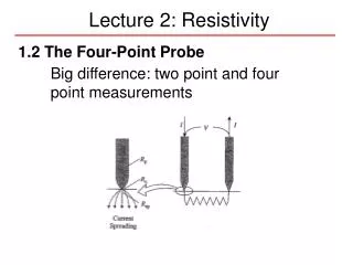
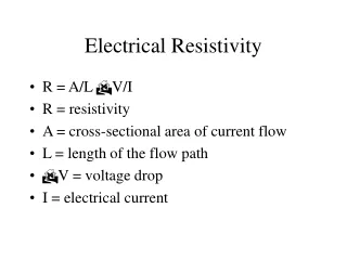
1.1. The resistivity method. Electric field in the ground (1) Shown in Fig.1 is the pattern of the field caused by two grounded current electrodes «A» and «B». This figure is commonly used to explain the theoretical basis of the resistivity method. The formulae describe the d.c. electric field in the ground. The field pattern, however, is not complete. It does not show electric field lines in the air. The air may be considered as an ideal insulator, which prevents the galvanic current flow. Therefore, the current density lines cannot describe the electric field in the air. Is this an evidence of nonexistence of the electric field in the air?
1.2. Electric field in the ground and in the air (2) In order to give the answer to this question let us consider Fig.2. The electric field pattern and the known equations describe the general case of field calculations where a interface divides two homogeneous media with resistivities «1» and «2». Calculating the limit of the expression (2) it is easy to derive the equations (1) which now describe electric fields in the air and in the ground. The pattern of the static electric field in the air (equipotential lines and lines of force of the field intensity) turned out to be a mirror image of the pattern of the stationary electric field in the ground, as shown in Fig.2.
1.3. Electric field in the ground and in the air (2) As can be seen from Fig.2, the horizontal component of the electric field at the central part of the «AB» line decreases equally slow as the observation point moves away in both directions from the earth-air interface. It means that the height dependence of this field component is extremely small and can be neglected when observations are made at heights comprising 1-5 % of length of the «AB» line. The vertical component of the electric field in the air at the central part of the «AB» line is much smaller than the horizontal component.
1.4. Electric field in the ground and in the air (2) Thus, when the electric field is measured in the air near the earth-air interface, the obvious physical basis for the proposed improvement is the known equality of the tangential components of the electric field on both sides of the interface. This allows to substitute contact measurements of the electric field using galvanically grounded measuring electrodes by contactless measurements with the use of receiving electric antennae (electrodes), which either have no galvanic contact with the ground at all or the contact is extremely poor.
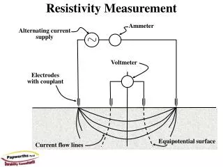
2. The measurements of the electric field in the ground Fig.1 (slide 3) shows a conventional grounded «MN» line. Fig.3 shows the same line on an enlarged scale. The equivalent electrical circuit of the receiving line (Fig.3) includes e.m.f. «U» (of the potential difference of the measuring electrodes) and the microvoltmeter input resistance «Rin» and the ground resistances of the measuring electrodes «RM» and «RN». From the equation in Fig.3 it is inferred that the input voltage «Uin», measured by the microvoltmeter, is almost equal to the potential difference «U» at favorable grounding conditions when the sum of resistances (RM+RN) is sufficiently small compared to the microvoltmeter input resistance. From the measured value «U» and known electrode separation «a» the intensity «Ex» of the electric field horizontal component can be easily calculated: Ex = U /a.
3.1. The measurements of the electric field in the air The non-grounded receiving line made up of two similar line electrodes «M» and «N» is shown in Fig.2 (slide 6) and Fig.4 (on an enlarged scale). The electrode separation «a» is here also the distance between the electrode centers. A distance«a» - is the effective length of an antenna. The line «MN» made up of two lengths of insulated wire may be either laid out directly on the ground surface or raise to a considerable height. The receiving line electrodes acquire the potentials of the equipotential lines through the centers of the electrodes. The equivalent electrical circuit of the line «MN»(Fig.4) includes the e.m.f. «U» and the capacitance voltage divider formed by the microvoltmeter-input impedance and self-capacitances «CM» and «CN» of the measuring electrodes.
3.2. The measurements of the electric field in the air In order to select an operating frequency let us consider the equivalent circuit of the array in Fig.4. At d.c. the desired signal «UIN» is zero. As the frequency rises the circuit transforms into a frequency-independent voltage divider. At a sufficiently small input capacitance «CIN» the desired signal is practically equal to the e.m.f. value "U" being measured. Calculations of the electric field intensity can be made from the equation, which was given before for the grounded receiving line. When selecting the optimal operating frequency, conflicting consideration must be given to the following discrepancies.
3.3. The measurements of the electric field in the air On the one hand, lower frequencies provide greater depths of investigation of the resistivity method. On the other hand, higher frequencies enable a more effective rejection of vibrational interferences, which are specific for the array in question. These interferences are due to the e.m.f. of electrization of the ungrounded line insulators. The interferences are considerable in magnitude and have an essentially low-frequency spectrum. The investigations revealed that optimal frequencies range from 20 to 3000 Hz. A basic frequency selected for developed system "ERA" is 625 Hz.
4.1. The anomalous electric fields in the air Let us focus on the nature of anomalous electric fields in the air to be measured by the resistivity method. Fig.5 shows a vertical high-resistivity layer a limited depth, which is a local causative body of anomaly. In a normal electric field with horizontal polarization the layer is polarizedand its vertical sides acquire stationary electric charges. This is the cause of anomalous electric currents and corresponding electric fields. Since galvanic currents must not penetrate into the insulator (air), static electric charges appear on the surface preventing the current flow from the ground into the air. The distribution of these charges is fully determined by the current flow pattern in the ground, and hence, the electric field of these charges in the air reflects this pattern.
4.2. The anomalous electric fields in the air Fig.5 shows the curves of the horizontal «Ex» and vertical «Ez» components of the anomalous electric field in the air in the vicinity of the earth-air interface. It may be noted that these curves are similar to the curves of the «Hx» and «Hz» components of an anomalous magnetic field over a vertical layer magnetized in the Earth's magnetic field in proximity to the equator.
5.1. Technology and equipment Depending on the spatial resolution required and the type of array, antennae of different designs (Fig.6)can be used. For example, an asymmetrical antenna (b) made up of insulated wires of up to 100 m in length creeping over the ground (a «snake»-like antenna) or a telescopic symmetrical air antenna (d) with an effective length of up to 1.5 m.
5.2. Technology and equipment In some types of arrays the operator caring a microvoltmeter may serve himself as one of measuring electrodes («N») with the other electrode («M») being non-grounded («snake» line).
5.3. Technology and equipment Fig.8 shows the transmitting lines for the gradient array: a – usual galvanically grounded line; b, c – non-grounded lines. b – «capacitive» line (unclosed loop),c - «inductive» line (closed loop).
5.4. Technology and equipment Fig.9 shows the dipole - dipole array: a – non-grounded array, b – usual galvanically grounded array. A’A - transmitting line; MN – receiving line.
5.5. Technology and equipment Fig.10 Receiver Transmitter A electric survey system «ERA»(Electrical Research Apparatus) has been developed at the Research & Production Enterprise «ERA» (St. Petersburg) under the supervision of the author. The «ERA» system is provided with unique active potential electrodes (input capacitance 0.1 pF; input resistance 20 GOhm). The transmitter producing output voltage stepped up to 1-1.5 kV. A basic frequency 625 Hz. Fig.10 shows the last version «ERA» system- «ERA-MAX» developed by L.I. Dukarevich («RPE», 2002).
6.1. Case history of the field and city works • The resistivity method without groundings proposed the author in 1963 has been successfully used in USSR and Russia in geological prospecting, hydrogeology, engineering investigations, environmental and archaeological studies. • In 1981 the technique was approved for application in USSR territory of the Ministry of geology of the USSR. • The new technology essentially expands opportunities of resistivity and miss-a-la-masse methods. It is applied in variants of profiling (gradient and dipole-dipole arrays), sounding, 3D-vector air measurements with rotary electric field, etc. The advantages of technology are: • increasing the efficiency of the resistivity method by extending its application into the areas with unfavorable conditions of groundings; • cutting down labor expenditures by reducing the size of field crews; • widening the scope of functional potentialities of the method in particular by virtue of 3D-vector measurements of the electric field in the air.
6.2. Case history of the field works Fig.11 shows the apparent-resistivity graphs of the dipole-dipole arrays: a – usual galvanically grounded array, b – non-grounded array. Sayani, 1975. The size of the crew was reduced to 2 persons. 1, 3, 4 - metamorphic rocks, 2 - tectonic discontinuities, 5 – limestone.
6.3. Case history of the field works • Fig.12. Winter and summer-time measurements with gradient array. • The «AB» line length is 600m. • The receiver air telescopic antenna with effective length 1 m. • Winter-time electric survey was carried out on the ice. • Central Kareliya, 1980.
NEW VERTICAL ELECTRICAL SOUNDING SET forsmalland average depths (1-2000 m) Journal “Geoecology, engineering geology, hydrogeology, geocryology ”, 2005, № 5, p.p.454-462 Standard interpretation program IPI2WIN (Moskva State University, Bobachev A.A.) • Features • high degree of protection of measurements from induction and capacitor distortions • the small sizes and the big resolution of survey (length of new set is • almost twice less then usual set) • increase of productivity survey (only one the receiving electrode “M” moves, • but all others one are grounded only once) • small number of a field staff (1-2 persons instead of 3) • possibility of "contactless" measurements (in bad grounding conditions) VES set schemes Induction effect with new and usual VES set Interpretation VES (new set) Spain, El Saltador а – cross-section “ρa”; b – geoelectrical cross-section; 1 – dry overburden, 1500 Ohm▪m; 2 – aeration zone conglomerates, 300 Ohm▪m; 3 – clay, 20 Ohm▪m; 4 – saturated conglomerates, 50÷60 Ohm▪m; 5 – marl (waterproof stratum), 5÷7 Ohm▪m. a – usual (symmetrical), b – new (with the transmitter in line MN),1 – receiver, 2 – transmitter, 3 – the coil with a wire Experimental (a, b) and theoretical (c) VES curves: a, c – new set ( the effect is absent ); b – usual (symmetricаl) set (the interpretation is distort by the effect); c – the new set VES theoretical curve; d – parameters of the two-layer geoelectrical cross-section; 1, 2 – dry (1) and damp (2) alluvium; 3 – marl (waterproof stratum)
6.4. Case history of the field works Fig.13. Grounded and non-grounded VES arrays for winter-time measurements on the river Zeya ice: a - comparison of VES curves for different frequencies and arrays; b - VES profile with geological cross-section. Amur region, 1996. 1- ice, 2- water, 3 – alluvium, 4 – eluvium, 5 – limestone.
6.5. Case history of the city works Fig.14 shows the ground electric resistivity map of a road cloth of the city prospectus in a zone of the emergency leakage of the high pressure mains water supply pipeline (1000 mm). The main unloading of the leakage happened here on ferro-concrete box of the adjacent central heating pipeline. However, the resistivity method has shown, that a part of the water flow percolated under asphalt pavement as two sleeves of a water saturated ground (zone 1 and 2). Saint-Petersburg, 1999. 1- water saturated ground zones; 2 – water supply pipeline with a leakage location; 3 – sewerage with a man-hole; 4 – central heating pipeline; 5 – curbstone.
6.6. Case history of the city works Fig.15. On the electrical survey data the extensive zone of the water saturated ground caused by leaks of the sewage disposal plant channel was established. The said zone is marked on the ground electric resistivity map (Fig.15а) by area of low resistivity 0.5-15 Ohm.m. The leakage location of the western «1» and east «2» channel walls was executed with the help of VES. Fig.15 The number of the electric resistivity VES sections for outside (profile 58) and inside (profiles 20, 18, 16) of the leakage area is shown on Fig.15b. The proposed innovative technology is an adequate competitor to the widely used ground penetrating radar technology.
7. Conclusion The resistivity method without groundings is a reality! It lives and works in Russia already more than 30 years.