Download
1 / 17
620 likes | 1.54k Vues
Chapter 12– Magnetic Circuits . Introductory Circuit Analysis Robert L. Boylestad. 12.1 - Introduction. Magnetism is an integral part of almost every electrical device used today in industry, research, or the home.

E N D
Chapter 12– Magnetic Circuits Introductory Circuit Analysis Robert L. Boylestad
12.1 - Introduction • Magnetism is an integral part of almost every electrical device used today in industry, research, or the home. • Generators, motors, transformers, circuit breakers, televisions, computers, tape recorders and telephones all employ magnetic effects to perform a variety of important tasks.
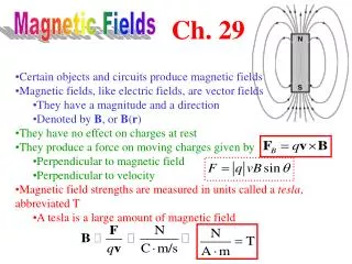
12.2 – Magnetic Field Flux and Flux Density • In the SI system of units, magnetic flux is measured in webers (Wb) and is represented using the symbol . • The number of flux lines per unit area is called flux density (B). Flux density is measured in teslas (T). • Its magnitude is determined by the following equation:
Magnetic Fields Permeability • Magnetic materials, such as iron, nickel, steel and alloys of these materials, have permeability hundreds and even thousands of times that of free space and are referred to as ferromagnetic. • The ratio of the permeability of a material to that of free space is called relative permeability.
12.3 – Reluctance • The resistance of a material to the flow of charge (current) is determined for electric circuits by the equation • The reluctance of a material to the setting up of magnetic flux lines in a material is determined by the following equation
12.4 – Ohm’s Law For Magnetic Circuits • For magnetic circuits, the effect is the flux . • The cause is the magnetomotive force (mmf) F,which is the external force (or “pressure”) required to set up the magnetic flux lines within the magnetic material. • The opposition to the setting up of the flux is the reluctance .
Ohm’s Law For Magnetic Circuits • Substituting • The magnetomotive force F is proportional to the product of the number of turns around the core (in which the flux is to be established) and the current through the turns of wire
12.5 – Magnetizing Force • The magnetomotive force per unit length is called the magnetizing force (H). • Magnetizing force is independent of the type of core material. • Magnetizing force is determined solely by the number of turns, the current and the length of the core.
12.6 – Hysteresis • Hysteresis – The lagging effect between the flux density of a material and the magnetizing force applied. • The curve of the flux density (B) versus the magnetic force (H) is of particular interest to engineers.
Hysteresis • The entire curve (shaded) is called the hysteresis curve. • The flux density B lagged behind the magnetizing force H during the entire plotting of the curve. When H was zero at c, B was not zero but had only begun to decline. Long after H had passed through zero and had equaled to –Hd did the flux density B finally become equal to zero
12.7 – Ampère’s Circuital Law • Ampère’s circuital law: The algebraic sum of the rises and drops of the mmf around a closed loop of a magnetic circuit is equal to zero; that is, the sum of the rises in mmf equals the sum drops in mmf around a closed loop. F = 0
12.8 – Flux The sum of the fluxes entering a junction is equal to the sum of the fluxes leaving a junction. a=b+ c or b +c= a both of which are equivalent
12.9 – Series Magnetic Circuits: Determining NI • Two types of problems • is given, and the impressed mmf NI must be computed – design of motors, generators and transformers • NI is given, and the flux of the magnetic circuit must be found – design of magnetic amplifiers • Table method • A table is prepared listing in the extreme left-hand column the various sections of the magnetic circuit. The columns on the right are reserved for the quantities to be found for each section
12.10 - Air Gaps Effects of air gaps on a magnetic circuit • The flux density of the air gap is given by where g = core Ag = Acore • Assuming the permeability of air is equal to that of free space, the magnetizing force of the air gap is determined by • And the mmf drop across the air gap is equal to Hg Lg
12.11 – Series-Parallel Magnetic Circuits Close analogies between electric and magnetic circuits will eventually lead to series-parallel magnetic circuits similar in many respects to electric circuits encountered previously (in Chapter 7).
12.12 – Determining • When determining magnetic circuits with more than one section, there is no set order of steps that will lead to an exact solution for every problem on the first attempt. • Find the impressed mmf for a calculated guess of the flux and then compare this with the specified value of mmf. • Make adjustments to the guess to bring it closer to the actual value. • For most applications, a value within 5% of the actual or specified NI is acceptable.
12.13 – Applications • Speaker and microphones • Hall effect sensor • Magnetic reed switch • Magnetic resonance imaging