Download
1 / 10

E N D
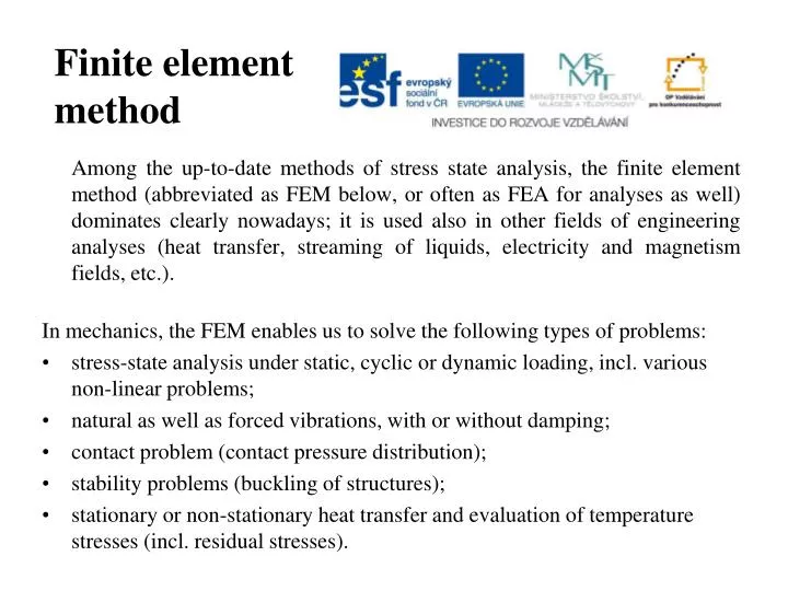
Finite element method Among the up-to-date methods of stress state analysis, the finite element method (abbreviatedas FEM below, oroften as FEA foranalyses as well) dominates clearly nowadays; it is used also in other fields of engineeringanalyses (heat transfer, streaming of liquids, electricity and magnetismfields, etc.). In mechanics, the FEM enables us to solve the following types of problems: • stress-state analysis under static, cyclic or dynamic loading, incl. various non-linearproblems; • natural as well as forced vibrations, with or without damping; • contactproblem (contactpressuredistribution); • stability problems (buckling of structures); • stationary or non-stationary heat transfer and evaluation of temperature stresses (incl. residualstresses).
Functional The fundamentals of FEM are quite different from the analytical methods of stress-strainanalysis. While the analytical methods of stress-strain analysis are based on the differentialand integral calculus, FEM is based on the variation calculus which is generallynot so well known; it seeks for a minimum of some functional. Explanation of the concept – analogy with functions: • Function - is a mapping between sets of numbers. It is a mathematical term for a rulewhich enables us to assign unambiguously some numerical value (from the image of mapping)to an initial numerical value (from the domain of mapping). • Functional - is a mapping from a set of functions to a set of numbers. It is a rule whichenables us to assign unambiguously some numerical value to a function (on the domainof the function or on its part). Definite integral is example of a functional.
Principle of minimum of the quadratic functional Among all the allowable displacements (i.e. those which meet the boundary conditions of the problem, its geometric and physical equations), only those displacements can come into existence between two close loading states (displacement change by a variation δu) which minimize the quadratic functional ΠL. This functional (called Lagrange potential) represents the total potential energy of the body, and the corresponding displacements, stresses and strains minimizing its value represent the seeked elasticity functions. This principle is called Lagrange variation principle. Lagrange potential can be described as follows: ΠL = W – P where W - total strain energy of the body P – total potential energy of external loads
Basic concepts of FEM • Finite element – a subregion of the solved body with a simple geometry. • Node – a point in which the numerical values of the unknown deformation parameters are calculated. • Base function – a function describing the distribution of deformation parameters (displacements) inside the element (between the nodes). • Shape function – a function describing the distribution of strains inside the element, it represents a derivative of the base function. • Discretization – transformation of a continuous problem to a solution of a finite number of non-continuous (discrete) numerical values. • Mesh density – it influences the time consumption and accuracy of the solution. • Matrixes (they are created by summarization of contributions of the individual elements) • of displacements • of stiffness • of base functions • Convergence – a property of the method, the solution tends to the reality (continuous solution) when the mesh (discretization) density increases. • Percentual energy error gives an assessment of the total inaccuracy of the solution, it represents the difference between the calculated stress values and their values smoothed by postprocessing tools used for their graphical representation, transformed into difference in strain energies. • Isoparametric element – element with the same order of the polynoms used in description of both geometry and base functions.
Stress distribution in the dangerous cross section of the notch
Overview of basic types of finite elements They can be distinguished from the viewpoint of assumptions the element is based on (bar assumptions, axisymmetry, Kirchhoff plates, membrane shells, etc.), or for what a family of problems the element is proposed. • 2D elements (plane stress, plain strain, axisymmetry) • 3D elements (volume elements - bricks) • Bar-like elements (either for tension-compression only, or for flexion or torsion as well) • Shell elements • Special elements (with special constitutive relations, contact or crack elements, etc.)
Basic types of constitutive relations in FEA • linear elastic anisotropic (elastic parameters are direction dependent, monocrystals, wood, fibre composites or multilayer materials), • elastic-plastic (steel above the yield stress) with different types of the behaviour above the yield stress (perfect elastic-plastic materials, various types of hardening), • non-linear elastic (deformations are reversible, but non-linearly related to the stress), • hyperelastic (showing elastic strain on the order of 101 – 102percents, • non-linear always as well), • viscoelastic (deformation is time-dependent additionally, the material shows creep, stress relaxation and hysteresis), • viscoplastic (their plastic deformation is time-dependent), etc.
Example of a non-linear problem:a FE mesh in a plastic guard of a pressure bottle valve