Download
1 / 14
160 likes | 482 Vues
Frequency response of feedback amplifiers. In previous context of discussion for feedback amplifiers, it is assumed that open-loop gain and feedback ratio are independent of frequency.

E N D
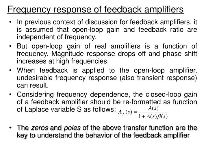
Frequency response of feedback amplifiers • In previous context of discussion for feedback amplifiers, it is assumed that open-loop gain and feedback ratio are independent of frequency. • But open-loop gain of real amplifiers is a function of frequency. Magnitude response drops off and phase shift increases at high frequencies. • When feedback is applied to the open-loop amplifier, undesirable frequency response (also transient response) can result. • Considering frequency dependence, the closed-loop gain of a feedback amplifier should be re-formatted as function of Laplace variable S as follows: • The zeros and poles of the above transfer function are the key to understand the behavior of the feedback amplifier
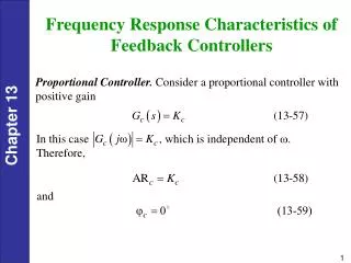
Transient response in terms of pole location • Remember from the Circuit Analysis Course, the mathematical form of the transient response is related to the location of the poles in the complex domain. • Obviously, we do not want to have poles on the positive real axis, because the transient response eventually drives the amplifier into voltage limits, resulting in nonlinear distortion. • Approximately within 5 time constant, the amplitude of exp terms decays to negligible value compared to initial amplitude. • The greater the distance of the pole from the origin, the faster the transient response decays
Effects of feedback on pole: one pole I • Negative feedback has dramatic effects on pole locations of amplifiers (OpAmp), which in turn affects transient response and frequency response of the amplifiers • First, considering a one-pole (or dominant pole) amplifier, the open loop gain is of the form • With feedback in this amplifier, then the closed-loop gain
Effects of feedback on pole: one pole II • Transient and frequency response of feedback amplifiers are related to the pole location, so we need to consider how the pole would change as feedback ratio changes • For single-pole (dominant-pole) amplifier, the pole for the closed-loop gain becomes • So, the above pole is still on the negative real axis, but moves further from the origin as increases • Real amplifiers usually have more than one pole. However, sometimes one pole is much closer to the origin than others (called dominant pole). In that case, we can ignore the rest of the poles. • Summary: for one-pole amplifier, the feedback back leads to a smooth roll-off of the frequency response and fast decaying of the transient response without ringing
Effects of feedback on pole: two pole I • Now, considering a two-pole amplifier, the open loop gain is of the form • Again assume feedback ratio is constant (not a function of frequency) and evaluate the poles of the closed loop transfer function • For the poles, as increases, the poles move together until they meet at the point in the middle. Then, further increase causes the poles to become complex, moving away from the real axis along the vertical line across the meeting point. (the path followed by the poles is called a root locus)
Effects of feedback on pole: two pole II • Usually, feedback amplifiers are designed so that is much larger than unity, which is usually necessary to achieve gain stabilization, impedance control, nonlinear distortion reduction etc. • From the root locus, it can be seen that a too large value of might move the poles outside the desirable region of the s-plane (the 45 degree negative axis). In that case, undesirable frequency response peaks and transient ringing occurs.
Example of a two-pole amplifier: Transient response Frequency response
Effects of feedback on pole: three poles • An amplifier with three or more poles can be analyzed using the same method as in the one pole and two poles case, but math analysis get much more complicated. • Qualitatively, in three poles case, feedback can cause the poles to move even to the right half of the complex plane, thus making the amplifier instable. • Example root lotus for 3 poles and 4 poles are shown below:
Example of a two-pole amplifier: Transient response