Download
1 / 29
330 likes | 580 Vues
CORRELATION BETWEEN RADIATED IMMUNITY AND COUPLING ATTENUATION Michiel Pelt. Need for new test method: No test methods to measure: symmetrical cables, connecting hardware / cable assemblies balance at higher frequencies combined effect of balance and screening. Introduction.

E N D
CORRELATION BETWEEN RADIATED IMMUNITY AND COUPLING ATTENUATION Michiel Pelt
Need for new test method: No test methods to measure: symmetrical cables, connecting hardware / cable assemblies balance at higher frequencies combined effect of balance and screening Introduction
Coupling attenuation New and easy test method to evaluate the EMC performance of channels and components (symmetrical + screened) Standard prepared by CENELEC TC 46X / WG3: EN 50289-1-6 Under discussion in ISO / IEC JTC1 SC25 WG 3 and CLC TC 215 WG 1 Introduction
A near field measurement Introduction
Simplifications Device under test: unshielded twisted pair cable coaxial cable dual foil balanced cable Radiated immunity according to IEC 61000-4-3 fixed position antenna and device Introduction
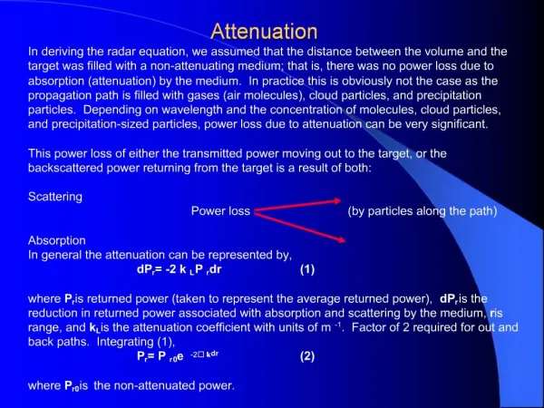
Coupling attenuation Coupling attenuation
Definition coupling attenuation Coupling attenuation ac = 10 LOG10 ( P1) max[ P2n; P2f ] ac coupling attenuation P1 input power inner circuit P2n maximum near end peak power P2f maximum far end peak power
Limits of coupling attenuation Coupling attenuation
Unshielded twisted pair cable Coupling attenuation 54 dB
Coaxial cable Coupling attenuation 52 dB
Dual foil twisted pair cable Coupling attenuation 86 dB
Radiated immunity Semi-anechoic room (13.2 x 4.7 x 3.0m) Antenna - set-up: 3 m Three amplifiers, two antennas 30 - 200 MHz 200 - 500 MHz 500 - 1000 MHz Incident field: about 3 V/m (not modulated) Radiated immunity
Dimensions cabling set-up Radiated immunity
Justification for cabling set-up Testing active equipment with cabling (proposal to CISPR G) Features cabling set-up: gain / frequency response flat polarization not critical direction not critical (worst case perpendicular to incident field) Radiated immunity
Set-up inside semi-anechoic chamber Radiated immunity
Set-up inside semi-anechoic chamber Radiated immunity
Uniform area of cabling set-up Radiated immunity
Field uniformity according to IEC 61000-4-3 16 points over 1.5 m x 1.5 m surface 75 % values within 0 - 6 dB of nominal value Field is not constant but uniform ( 83% horizontal; 89 % vertical) Radiated immunity
Average field strength Radiated immunity
Unshielded twisted pair cable Radiated immunity -35 dBm
Coaxial cable Radiated immunity -35 dBm
Dual foil twisted pair cable Radiated immunity -70 dBm
Conclusion 1: Relative agreement Same difference between coupling attenuation and induced power for all tested cables For each test method same deviation between curves for balanced and unbalanced cables using Conclusions
Gain of set-up Correlation G() = 4 Af() G( antenna gain Af( antenna aperture wavelength
Unshielded twisted pair cable Correlation
Coaxial cable Correlation
Dual foil twisted pair cable Correlation
Conclusion 2: Absolute agreement The induced noise power can be calculated using the values for coupling attenuation The calculated induced power fits the measured powers for all cables Conclusions
Errors during correlation Incident field uniform but not constant Gain set-up varies with frequency Coupling attenuation approached by envelope curve ... Conclusions