Download
1 / 29
300 likes | 616 Vues
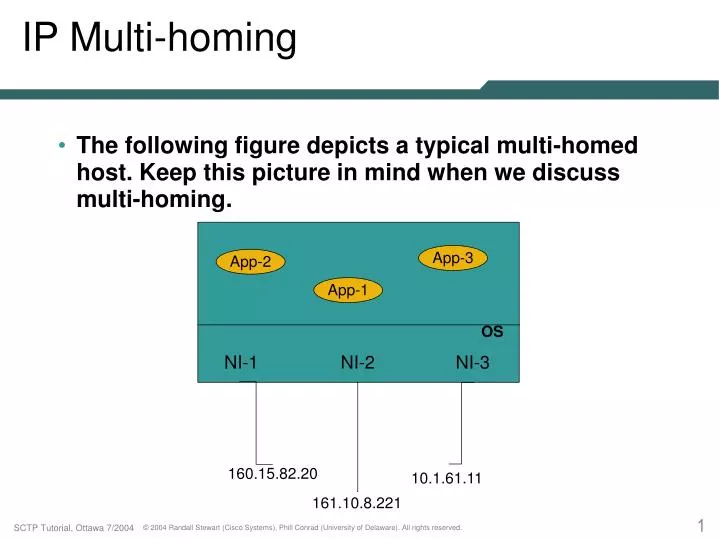
App-3. App-2. App-1. OS. NI-1. NI-2. NI-3. 160.15.82.20. 10.1.61.11. 161.10.8.221. IP Multi-homing. The following figure depicts a typical multi-homed host. Keep this picture in mind when we discuss multi-homing. Multi-homed Considerations.

E N D
App-3 App-2 App-1 OS NI-1 NI-2 NI-3 160.15.82.20 10.1.61.11 161.10.8.221 IP Multi-homing • The following figure depicts a typical multi-homed host. Keep this picture in mind when we discuss multi-homing.
Multi-homed Considerations • When a peer is multi-homed, a “primary destination address” will be selected by the SCTP endpoint. • By default, all data will be sent to this primary address. • When the primary address fails, the sender will select an alternate primary address until it is restored or the user changes the primary address. • SACK's may also require some special handling, consider the following:
IP-1 IP-2 EP-1 EP-2 IP-4 IP Network IP-3 A Multi-homed Peer With a Failure X
Special Considerations • If IP-2 was EP-2's primary address, then the association may still fail even though EP-1 has multiple addresses. [more on association failures later] • In the preceding drawing imagine that EP-1 is sending packets with source address IP-2. • If EP-2 always sends SACK’s back to IP-2, EP-1 will never receive a SACK. • To prevent this, a receiver will generally alter the destination address of a SACK if it receives duplicate data.
Failure Detection and Recovery • SCTP has two methods of detecting fault: • Heartbeats • Data retransmission thresholds • Two types of faults can be discovered: • An unreachable address • An unreachable peer • A destination address may be unreachable due to either a hardware or network failure
Endpoint-1 Endpoint-2 NI-1 NI-2 NI-1 NI-2 IP Network X IP Network Unreachable Destination Address
Unreachable Peer Failure • A peer may be unreachable due to either: • A complete network failure • Or, more likely, a peer software or machine failure • To an SCTP endpoint, both cases appear to be the same failure event (network failure or machine failure). • In cases of a software failure if the peers SCTP stack is still alive the association will be shutdown either gracefully or with an ABORT message.
Endpoint-1 Endpoint-2 NI-1 NI-2 NI-1 NI-2 IP Network X IP Network X Unreachable Peer: Network Failure
Endpoint-1 Endpoint-2 NI-1 NI-2 NI-1 NI-2 IP Network IP Network Unreachable Peer: Endpoint Failure
Heartbeat Monitoring Mechanism • A HEARTBEAT is sent to any destination address that has been idle for longer than the heartbeat period • A destination address is idle if no chunks that can be used for RTT updates have been sent to it • e.g. usually DATA and HEARTBEAT • The heartbeat period timer is reset any time a DATA or HEARTBEAT are sent • The peer responds with a HEARTBEAT-ACK
Unreachable Destination Detection • Each time a HEARTBEAT is sent, a Destination Error count for that destination is incremented. • Any time a HEARTBEAT-ACK is received, the Error count is cleared. • Any time DATA is acknowledged that was sent to a destination, its Error count is cleared. • Any time a DATA T3-rtx timeout occurs on a destination, the Error count is incremented. • Any time the Destination Error count exceeds a threshold (usually 5), the destination is declared unreachable.
Unreachable Destination II • If a primary destination is marked “unreachable”, an alternate is chosen (if available). • Heartbeats will continue to be sent to “unreachable” addresses. • If a Heartbeat is ever answered, the Error count is cleared and the destination is marked “reachable”. • If it was the primary destination and no user intervention has occurred, it is restored as the primary destination.
Unreachable Peer I • In addition to the Destination Error count, an overall Association Error count is also maintained. • Each time a Destination Error count is incremented, so is the Association Error count. • Each time a Destination Error count is cleared, so is the Association Error count. • If the Association Error count exceeds a threshold (usually 8), the peer is marked as unreachable and the association is torn down.
Unreachable Peer II • Note that the two control variables are seperate and unrelated (i.e. Destination Error threshold and the Association Error threshold). • It is possible that ALL destinations are unreachable and yet the Association Error count has not exceeded its threshold for association tear down. • This is what is known as being in the Dormant State. • In this state, MOST implementations will at least continue to send to one address.
Other Uses for Heartbeats • Heartbeat is also used to calculate RTT estimates • The standard Van Jacobson SRTT calculation is done on both DATA RTTs or Heartbeat RTTs • Just after association setup, Heartbeats will occur at a faster rate to “confirm” addresses • Address Confirmation is a new concept added in Version 10 of the I-G
Address Confirmation • All addresses added to an association via INIT or INIT-ACK's address lists that were NOT supplied by the user or used to exchange the INIT and INIT-ACK are considered to be suspect. • These address are marked unconfirmed and CANNOT be marked as the primary address. • A Heartbeat with a 64-bit nonce must be sent and an Heartbeat-Ack with the proper nonce returned before an address can leave the unconfirmed state.
Endpoint-1 Endpoint-2 IP-Z IP-X IP-B IP Network IP Network Init(IP-A,IP-B) Evil-3 IP-A IP Network Why Address Confirmation
Heartbeat Controls • Heartbeats can be turned on and off. • Heartbeats have a default interval of 30 seconds. This can also be adjusted. • The Error thresholds can be adjusted: • Each Destination's Error threshold • Overall Association Error threshold • Care must be taken in making any adjustments as false failure detections may occur.
Heartbeat Controls II • All heartbeats have a random delta (jitter) added to them to prevent synchronization. • The heartbeat interval will equate to • RTO + HB.Interval + (delta). • The random delta is +/- 0.50 of RTO. • Unanswered heartbeats cause RTO doubling.
Network Diversity and Multi-homing • Multi-homing can assist greatly in preventing single points of failure • Path diversity is also needed to prevent a single point of failure • Consider the following two networks with maximum path diversity and minimal path diversity: • Both hosts are multi-homed, but which network is more desirable?
Endpoint-1 Endpoint-2 Maximum Path Diversity
Endpoint-1 Endpoint-2 Minimum Path Diversity
Asymmetric Multi-homing • In some cases, one side will be multi-homed while the other side is singly-homed. • In this configuration, a single failure on the multi-homed side may still disable the association. • This failure may occur even when an alternate route exists. • Consider the following picture:
1.2 1.1 Endpoint-1 Endpoint-2 3.1 3.2 2.1 2.2 E-1 Route Table E-2 Route Table 3.0 -> 1.2 1.0 -> 3.2 2.0 -> 3.2 Aysmmetric Multi-Homing
Solutions to the Problem • One possible solution is shown in the next slide. • One disadvantage is that an extra route must be added to the network, thus using additional address space. • Routing setup is more complicated (most hosts like to use simple default routes)
1.2 1.1 Endpoint-1 Endpoint-2 3.1/4.1 3.2 2.1 2.2 E-1 Route Table E-2 Route Table 3.0 -> 1.2 1.0 -> 3.2 4.0 -> 2.2 2.0 -> 3.2 Solution 1
A Simpler Solution • A simpler solution can be made by the assitance of the multi-homed host’s routing table. • It first must be setup to allow duplicate routes at any level in its routing table. • Support must be added to query the routing table for an “alternate” route. • When SCTP hits a set error threshold, it asks for an “alternate” route then the previously cached one .
1.2 1.1 Endpoint-1 Endpoint-2 3.1 3.2 2.1 2.2 E-1 Route Table E-2 Route Table Default -> 1.2 1.0 -> 3.2 2.0 -> 3.2 Default -> 2.2 Solution 2
ADD-IP Extensions • The ADD-IP draft allows dynamic changes to an address set of an endpoint without restart of the association.