Download
1 / 29
290 likes | 516 Vues
Lect 12: Interrupt and Exception. Types of Interrupts and Exceptions. Interrupt service routine :. Types of Interrupts and Exceptions. up to 256 Interrupts Interrupt types and their priority External HW interrupts Non-maskable interrupt SW interrupts Internal Interrupts and exceptions

E N D
Types of Interrupts and Exceptions • Interrupt service routine :
Types of Interrupts and Exceptions • up to 256 Interrupts • Interrupt types and their priority External HW interrupts Non-maskable interrupt SW interrupts Internal Interrupts and exceptions Reset Increasing Priority
Interrupt Vector Tables • Interrupt Vector Table: • In a real-mode:
23 16 15 8 7 0 32 24 DWORD COUNT 0 0 0 4 P DPL 0 111T OFFSET 31..16 7 3 OFFSET 15 .. 0 SELECTOR 0 Interrupt Descriptor Table: • In a protected-mode: • Interrupt gate, trap gate, task gate descriptors
Interrupt Procedures TSS Destination Code Segment Interrupt Vector Interrupt Vector Task Gate Offset Interrupt or Trap Gate TSS Descriptor Segment Descriptor
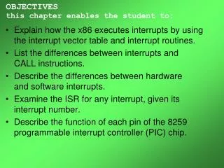
Exceptions and Interrupts • Interrupts • Non-maskable interrupt • Maskable interrupts • Exceptions • Processor-detected exceptions • Programmed Exceptions : INTO, INT3, INT n, BOUND • Types of Exceptions • Faults: reported at the instruction boundary prior to the instruction in which the exception was detected • can be restarted • CS and EIP -> fault instruction • Traps: reported at the instruction boundary immediately after the instruction in which the exception was detected • CS and EIP -> next instruction • Aborts: does not always report the location of the faulted instruction • does not allow restart of the pgm • severe error
82C59A Programmable Interrupt Controller • Features • CMOS • Programmable • Level-sensitive or edge-triggered • cascaded to expand from 8 to 74 interrupt inputs • wide variety of priority schemes • Block Diagram of the 82C59A
Interface signals • D7-D0: host interface • RD: status of IRR, ISR, IMR of the Interrupt Level • WR:(ICWs and OCWs) Initialization Command Words, Operation Command Words • A0: RD, WR • INT: interrupt request: level-sensitive • INTA, CAS2-CAS0 • SP/EN: slave or master (input: cascaded mode)/enable(output: single mode or buffered mode) • IRR : interrupt request register : store all interrupt levels • ISR : store all the interrupt levels which are being served • Priority resolver: determine the priorities; the highest priority is selected and stored into the corresponding bit of the ISR during INTA pulse • IMR: 1: mask out 0: enable
82C59A Programmable Interrupt Controller • Programming the 83C59A • Initialization Command Words(ICWs) • 2 ~ 4 bytes • Operational Command Words(OCWs) • Fully Nested Mode • Rotating Priority Mode • Special Mask Mode • Poll Mode • Initialization Sequence
82C59A Programmable Interrupt Controller • ICW Format
ICW Format • ICW3 format • master mode (SP=1 or in buffered mode when M/S=1 and BUF =1 in ICW4) • slave mode (SP =0 or if BUF=1 M/S=0 in ICW4) • IF BUF =1 the buffered mode is programmed. In buffered mode SP/EN becomes an enable output and the master/slave determination is by M/S • Special fully nested mode : only used in conjunction with the cascaded mode.
82C59A Basic Operation A D D RD WR CS 0 4 3 0 0 1 0 IRR, ISR or Interrupt Level -> Data Bus *IRR, ISR, Int. Level is based on the content of OCW 3 written before the READ op 1 0 1 0 IMR -> DataBus 0 0 0 1 0 0 DataBus -> OCW 2 0 0 1 1 0 0 DataBus -> OCW 3 0 1 x 1 0 0 DataBus -> ICW 1 1 x x 1 0 0 DataBus -> OCW , ICW , ICW , ICW 1 2 3 4
82C59A Basic Operation • Special Mask Mode • It inhibits further interrupts at that level and enables interrupts from all other levels(lower as well as higher) that are not masked • Buffered Mode • Bus buffers are required • Nested Mode • IR(priority from 0 to 7) -> ISR • Cleared by EOI or if AEOI, INTA • the same or lower priority are inhibited • IR0 has the highest priority • Special Fully Nested Mode • Cascaded Mode
82C59A Basic Operation • Poll Mode • disabling interrupt 1 - - - - w2 w1 w0 • W2 W1 W0 : binary code of the highest priority level requesting service • EOI(End of Interrupt) • IS bit : if AEOI bit in ICW4 is set, automatically reset the IS bit otherwise use OCW2 to reset the IS bit • EOI must be issued twice in the cascaded system: one for master and one for slave • Specific and Nonspecific EOI
AEOI Mode • IS bit is cleared by INTA signal • Rotating Priority Mode A (Automatic Rotation) for Equal Priority Devices • Before Rotate “IS” 0 1 0 1 0 0 0 0 0 1 0 0 0 0 0 0 priority 7 6 5 4 3 2 1 0 2 1 0 7 6 5 4 3 • non specific EOI; Automatic EOI(INTA) • Rotating Priority Mode B (Rotation By Software) • Programming the bottom priority • specific EOI low low high high