Download
1 / 28
280 likes | 417 Vues
AHIPA Workshop. Accumulation and Bunch Rotation Schemes. Chuck Ankenbrandt Muons, Inc. October 20, 2009. Another talk in a series…. Some people are so creative that they are able to bring different crazy ideas to every gathering. I’ll give (a new version of) the same crazy talk.

E N D
AHIPA Workshop Accumulation and Bunch Rotation Schemes Chuck Ankenbrandt Muons, Inc. October 20, 2009 Chuck Ankenbrandt AHIPA2009
Another talk in a series… • Some people are so creative that they are able to bring different crazy ideas to every gathering. • I’ll give (a new version of) the same crazy talk. • It seems to be gaining acceptance… • (by sane people?) • Since many of you have heard it before, I’ll try to • be brief, and • emphasize what’s new. • (Next slides show title pages of previous talks.) Chuck Ankenbrandt AHIPA2009
Low Emittance Muon Collider Workshop 2009 Project X and the Fermilab Muon Collider Chuck Ankenbrandt Muons, Inc. June 11, 2009 Chuck Ankenbrandt LEMC2009
Muon Collider Design Workshop Project X as a Proton Driver Chuck Ankenbrandt Muons, Inc. and Fermilab December 9, 2008 Chuck Ankenbrandt AHIPA2009
HB2008 Comparison of Proton Driver Schemes For Muon Collider and Neutrino Factory (There is a writeup in the HB2008 proceedings) Chuck Ankenbrandt1,2 and Rol Johnson1 Muons, Inc1 and Fermilab2 August 26, 2008 Chuck Ankenbrandt AHIPA2009
Introduction • Two customers: neutrino factory and muon collider • Two configurations: IC1 and IC2 • Question: What to add to the two configurations to serve the two customers. • It will be nice if there is one solution, not four. • Whatever is built initially should be directly useful for the MC/NF upgrade without major modifications. • So, how can Project X be used to drive a NF/MC? Chuck Ankenbrandt AHIPA2009
Introduction (cont.) • IC1 has an 8-GeV pulsed linac. • IC2 has a 2.x-GeV CW linac. • The IC2 linac has to be augmented to feed the MI. • Either an RCS from 2 to 8 GeV to MI via Recycler, • or a pulsed (?) linac from 2 to ?? GeV to MI directly. • The latter device would be more useful for MC/NF. • The IC2 hi-energy linac should be “pulsed” in a special way: the linac should “think” it is CW. • Question: to what energy should the IC2 linac go? • Roland Garoby thinks 5 GeV is enough for CERN neutrino factory based on SPL linac. • Maybe we’ll need more for MC? Chuck Ankenbrandt AHIPA2009
ISS Requirements (Feb. 3, 2008) accel 150 or 250 Hz Chuck Ankenbrandt AHIPA2009
Interesting footnote in ISS report Chuck Ankenbrandt AHIPA2009
Muon Collider Proton Driver Requirements Andreas Jansson Fermilab Chuck Ankenbrandt AHIPA2009
Muon Collider Parameters R. Palmer, LEMC 6/30/08 Chuck Ankenbrandt AHIPA2009 NuFact08, Valencia A. Jansson 11
Packaging (rep rate) CW linac has more flexibility to change frep . • Bunch rep rates range from 12-65Hz • Note that this is not necessarily the same as the proton driver rep rate. • Flexibility here would be useful, also for operations • This can be achieved using one or more intermediate fixed energy rings. 6/30/08 Chuck Ankenbrandt AHIPA2009 NuFact08, Valencia A. Jansson 12
Conclusions • A muon collider would likely need ~4MW of proton power • Should plan for a further upgrade potential of factor ~2 to cover shortfalls in cooling efficiency and future luminosity upgrades • Bunch rep rate on target ranges from 12-65 Hz • Not necessarily the same as linac rep rate. Flexibility can be achieved with intermediate fixed energy rings. • Proton driver energy is flexible, but at least at Fermilab 8GeV seems most attractive • Need more detailed study of intensity limitations. • Need to weigh cost of new 50GeV ring(s) against cost of Project X linac upgrades 6/30/08 Chuck Ankenbrandt AHIPA2009 NuFact08, Valencia A. Jansson 13
Comments on Requirements • Energy: • ISS said 5 < Ep < 15 GeV 8 GeV is ~ ideal. • Nm/(Np*Ep) peaks around 8 GeV • Fermilab has a lot of 8 GeV rings. • Bunch delivery: • Cycle rate of proton accelerator: ISS said 50 Hz • Bunches per cycle: ISS said 3 or 5 • The difficulty of the proton driver goes up as the number of proton bunches per second goes down. • 150 or 250 bunches per second for NF • ~ 15 to 60 for MC • Making rms bunch lengths of 3 nsec is a LOT easier than 2 nsec and reduces yield only ~5%. Chuck Ankenbrandt AHIPA2009
Linac Intensities • IC1 has an 8-GeV pulsed linac. • Power = Tp*Np/sec = Tp*I*dt*frep • Upgrade parameters for 4 MW: • Repetition rate: 20 Hz • Beam pulse duration: 1.3 msec or 1 msec • Average current during pulse: 20 mA or 27 mA • IC2 has a 2.x-GeV CW linac with <I> = 1 mA. • For CW case, dt*frep=1, so Power = Tp*<I>. • E.g. 5 MW at 5 GeV. • Can’t let the duty factor be much less than 1, so stay CW. • Ion source delivers 10 mA DC • Can chop 90% of beam so linac sees <I> = 1 mA • Max available beam power of CW linac is higher. Chuck Ankenbrandt AHIPA2009
Comparison with RCS • The RCS has a duty factor of .044, since it injects for 4.4 msec at 10 Hz. It boosts the energy from 2 to 8 GeV, so the power is • Power = 8 GeV * 1 mA * .044 = 350 kW. • RCS Upgrade to 4 MW looks very difficult. Chuck Ankenbrandt AHIPA2009
Desire for performance contingency • Advocates of low-emittance designs worry that very high intensities per bunch (of protons and/or muons) will not be feasible due to various intensity-dependent effects. • Advocates of high intensities per bunch worry that very low emittances will not be achievable. • What if both camps are right!?! Then a face-saving compromise path is needed: Raise the proton beam power (rep rate) if necessary. • E.g. 8 MW at 8 GeV from CW linac. Chuck Ankenbrandt AHIPA2009
Design concept • Two multi-GeV storage rings • An accumulator ring • A buncher ring • Question: 8 GeV for IC1, ?? GeV for IC2 • Question: can we get by with only one ring? • Add trombone plus funnel if necessary to reduce repetition rate of bunch arrivals at the target. • This external bunch-combiner might be added as part of what’s needed to transform from a neutrino factory to a muon collider facility. Chuck Ankenbrandt AHIPA2009
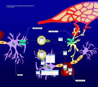
Providing p Bunches for a n Factory or a m Collider Ignore the details Chuck Ankenbrandt AHIPA2009 19
Essential new idea for IC2 • Issue: with a low-current CW linac, many more turns must be injected into the accumulator ring. The stripper foil sees many more turns passing. A pulsed linac is much better in this regard. • Solution: make CW linac effectively pulsed: • Chop linac beam so beam is there only every tenth turn. • (The high-Q linac cavities don’t notice the difference.) • Add a dipole 2-bump around the foil, oscillating at frev/10, to move the circulating beam away from the foil when the injected beam is off. Chuck Ankenbrandt AHIPA2009
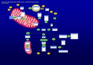
An external combiner (“trombone”)to reduce rep rate at target Several bunches enter Bunches exit simultaneously Chuck Ankenbrandt AHIPA2009
A specific hi rep. rate, 8 GeV example • Use Accumulator(-like) and Debuncher(-like) rings. • Acc and Deb are leftovers from Fermilab’s Antiproton Source • They are not very deep underground; maybe move them to a new tunnel? • Paint to large (~200 pi) transverse emittances in rings with small circumference to control space charge. • Could strip directly into “Accumulator” or do multi-turn transverse stacking from Recycler to “Accumulator”. • Small circumference means more favorable bunching factor. • Scale from space charge tune shift (~0.04) in Recycler ring. • Use h=12 and h=24 rf to make 12 ~rectangular bunches. • (Note possible constraints on h1, h2: Circumference ratio of the two rings, if multiple bunches are transferred) • Transfer three bunches at a time to the “Debuncher”. • Do a bunch rotation in the “Debuncher”. • Deliver three bunches at a time to the target at 60 Hz. Chuck Ankenbrandt AHIPA2009
Proton Driver Design Challenges • Design of the rings: rf, lattices, etc. • Multi-turn injection by stripping H- • ~1000 turns in IC1 • Even more in IC2 • Intensity-dependent effects • Each linac pulse delivers ~ 150 Tp • Space charge, electron cloud, instabilities • Beam delivery to the target • Desired rms beam size ~ 5 mm • Large transverse emittances to control space charge • Small beta function at the target • Trombone/funnel design (may be an upgrade path) • Target and dump design and performance • What have you? Chuck Ankenbrandt AHIPA2009
Tentative Conclusions • Both IC1 and IC2 might be usable for MC/NF. • The CW linac of IC2 should be extended to >~ 5 GeV. • One or two storage rings at the linac energy can provide the desired bunch structures with some flexibility in rep rates. • For IC2, the beam should be chopped, and an AC dipole two-bump around the foil should be added. • An external combiner can reduce the rep rate of bunches at the pion production target if necessary. • There are many design issues to be addressed. Chuck Ankenbrandt AHIPA2009
Backup slides Chuck Ankenbrandt AHIPA2009
Scaling of Muon Collider Requirements • The luminosity of a muon collider is given by the product of: • the integrated luminosity per muon bunch pair injected, times • the rep. rate Rb of injecting bunch pairs into the collider. Designers often assume (optimistically?) that the muon bunches can be made bright enough to reach the beam-beam limit. Then: • and for given luminosity, energy, and beam-beam tune shift: • the rep. rate scales inversely with the trans. emittance; • the proton beam power is independent of the trans. emittance. Chuck Ankenbrandt AHIPA2009
Scaling of PD params with collider energy • For given muon bunch parameters, the luminosity of an optimistically designed collider tends to scale like s, the square of the CM energy. • There’s one factor of energy in the non-normalized emittance; • The bunch length can also be reduced as the energy is raised, allowing smaller b*. • The cross sections for pointlike processes scale as 1/s. • As a result, the event rates depend only weakly on s. • Therefore, the requirements on the front end of an optimistically designed muon collider are approximately energy-independent. Chuck Ankenbrandt AHIPA2009
Space-charge tune shift scaling Scale from incoherent tune shift of 0.04 in Recycler The energy (8 GeV) and the total number of protons are the same in the Recycler and the Debuncher. The transverse stacking into the Debuncher raises the transverse emittances by a factor of eight. The bunching factor goes down (worse) by a factor of nine. Chuck Ankenbrandt AHIPA2009 28