Download
1 / 92
930 likes | 1.25k Vues
CHAPTER 16 MICROPROGRAMMED CONTROL. FOR : DR. H. WATSON. BY: FRANCISCO VASQUEZ SHINA AHMAD CARLOS FERNANDEZ NINGYUAN WANG MIGUEL RONDON CARLOS LAGUERRE MICHAEL BOZA. FLORIDA INTERNATIONAL UNIVERSITY – ENGINEERING CENTER SUMMER 2011. Chapter # 16: Microprogrammed Control. Topics:.

E N D
CHAPTER 16 MICROPROGRAMMED CONTROL FOR: DR. H. WATSON BY: FRANCISCO VASQUEZ SHINA AHMAD CARLOS FERNANDEZ NINGYUAN WANG MIGUEL RONDON CARLOS LAGUERRE MICHAEL BOZA FLORIDA INTERNATIONAL UNIVERSITY – ENGINEERING CENTER SUMMER 2011
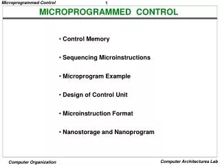
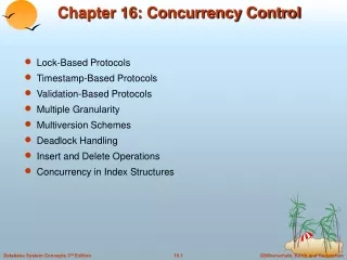
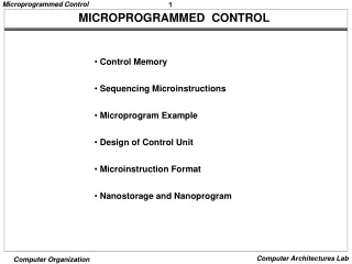
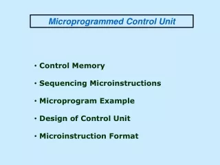
Chapter # 16: Microprogrammed Control Topics: • Basic Concepts • Microinstructions • Microprogrammed Control Unit • Wilkes Control • Advantages and Disadvantage • Microinstruction Sequencing • Design Considerations • Sequencing Techniques • Address Generation • LSI–11 Microinstruction Sequencing • Microinstruction Execution • A Taxonomy of Microinstructions • Microinstruction Encoding • LSI–11 Microinstruction Execution • IBM 3033 Microinstruction Execution • TI 8800 • Microinstruction Format • Microsequencer • Registered ALU
Chapter # 16: Microprogrammed Control Registers diagram:
Chapter # 16: Microprogrammed Control Basic Elements of a Processor: • ALU • Registers • Internal data paths • External data paths • Control Unit
Chapter # 16: Microprogrammed Control Functions of Control Unit: • Sequencing • Causes the CPU to step through a series of micro-operations • Execution • The Control Unit causes each micro-operation to be performed (Using control signals)
Chapter # 16: Microprogrammed Control Data Paths and Control Signals:
Chapter # 16: Microprogrammed Control Types of Micro-operations: • Transfer data between registers • Transfer data from register to external (Memory, I/O) • Transfer data from external to register • Performarithmetic or logical operations
Chapter # 16: Microprogrammed Control Microprogrammed Control: • A microprogram has a sequence of instructions in a microprogramming language. • This are very simple instructions that specify micro-operations.
Chapter # 16: Microprogrammed Control Microprogrammed Control: • As in a hardwired control unit, the control signal generated by a microinstruction are used to causeregister transfers and ALU operations . • Use sequences of instructions to control complex operations. • Called micro-programming or Firmware.
Chapter # 16: Microprogrammed Control Microprogrammed Control: • All the control unit does is generate a set of control signals. • Each control signal is on or off. • Represent each control signal by a bit. • Have a control word for each micro-operation. • Have a sequence of control words for each machine code instruction. • Add an address to specify the next micro-instruction, depending on conditions.
Chapter # 16: Microprogrammed Control Typical Microinstruction Formats:
Chapter # 16: Microprogrammed Control Organization of Control Memory:
Chapter # 16: Microprogrammed Control Control Unit:
Chapter # 16: Microprogrammed Control Functioning of Microprogrammed Control Unit:
Chapter # 16: Microprogrammed Control Processor block diagram example:
Chapter # 16: Microprogrammed Control Wilkes Control - Diode Matrix: A diode memory is just a collection of diodes connected in a matrix.
Chapter # 16: Microprogrammed Control Wilkes’s Microprogrammed Control Unit:
Chapter # 16: Microprogrammed Control Wilkes Control – key points: • Developed by Maurice Wilkes in the early 1950s • Matrix partially filled with diodes • During cycle, one row is activated • Generates signals where diode present • First part of row generates control • Second part generates address for next cycle
Chapter # 16: Microprogrammed Control Advantages and disadvantages: • Hardwired: • It is difficult to design and test such piece of hardware. • The design is relatively inflexible. For example to add a new instruction. • It is relatively faster. • Microprogrammed: • Simplifies design of Control Unit • Cheaper • Less error-prone • Slower
MICROINSTRUCTION SEQUENCING 1- Design Considerations 2- Sequencing Techniques 3- Address Generation 4- LSI-11 Microinstruction Sequencing
Design Considerations • Determined by Instruction Register • Next sequential address • Branch.
Sequencing Techniques • Two address fields • Single address field • Variable format
Two Address Fields Control address register Address Decoder Control memory Control Address 1 Address 2 Flags Branch logic Multiplexer Address Selection Instruction Register
Variable Format Address Decoder Control Memory Control Buffer Register Branch control field Control address register Entire Field +1 Address field Gate and function logic Multiplexer Branch logic Address Selection Flags Instruction Register
Description and Advantages • Introduced by M. V. Wilkes in 1951 • Storage of Micro-Instruction • Sequences • Hardwire Vs Micro-Instruction • Advantages & Disadvantages
Explicit Memory Address Generation • Address Location • Two Field Approach • Conditional Branch Instruction
Implicit Memory Address Generation • Control Memory • Mapping Approach • Adding Approach
Microinstruction Execution A Taxonomy of Microinstruction & Microinstruction Encoding Ninyuan Wang
Microinstruction Cycle • The basic event on a microprogrammed processor. • Two parts: fetch and execute. • Fetch: determined by the generation of a microinstruction address.
Execute • The effect of the execution of a microinstruction is to generate control signals. • Some of these signals control points internal to the processor. • The remaining signals go to the external control bus or other external interface. • As an incidental function, the address of the next microinstruction is determined.
A Taxonomy of Microinstructions Microinstructions can be classified in a variety of ways. Distinctions that are commonly made in the literature include the following: • Vertical/horizontal • Packed/unpacked • Hard/soft microprogramming • Direct/indirect encoding
How to Encoding • K different internal and external control signals to be driven by the control units. • In Wilkes’s scheme: • K bits of the microinstruction would be dedicated to this purpose. • possible combinations of control signals to be generated during any instruction cycle.
Not all be used – can do better • Two sources cannot be gated to same destination. • A register cannot be both source and destination. • Only one pattern of control signals can be presented to ALU at a time. • Only one pattern of control signals can be presented to external control bus at a time. • Require which can be encoded with bits.
In practice, this form of encoding is not used, for two reasons: • It is as difficult to program as pure decoded (Wilkes) scheme. • It is requires complex and therefore slow control logic module. • Instead, some compromises are made. These are of two kinds: • More bits than necessary used to encode the possible combination. • Some combinations that are physically allowable are not possible to encode.
Microinstruction Encoding • In practice, microprogrammed control units are not designed using a pure unencoded or horizontal microinstruction format. • The basic technique for encoding is illustrated in Figure 16.11a.
The microinstruction is organized as a set of fields. • Each field contains a code, which, upon decoding, activates one or more control signals. • The design of an encoded microinstruction format can now be stated in simple terms:
Organize the format into independent fields. • Each field depicts set of actions (pattern of control signals) • Actions from different fields can occur simultaneously • Alternative actions that can be specified by a field are mutually exclusive • Only one action specified for field could occur at a time
LSI-11 • First member of the PDP-11 family. • Offered as a single board processor. • Board consists of 3 LSI chips, internal bus, and interfacing logic.
Q bus • The Q-bus was one of several bus technologies used with PDP computer systems. • Over time, the physical address range of the Q-bus was expanded from 16 to 18 and then 22 bits. Block transfer modes were also added to the Q-bus.
LSI-11 cont. • The three LSI are the data, control, and control store chips.