Download
1 / 32

E N D
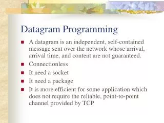
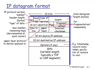
Data Encapsulation • As data leaves one host and arrives at another, it passes through the networking layers on both machines. Each layer performs a specific function. Data is encapsulated with a header at each layer. The header has fields containing values that specify exactly how a layer should perform. L. Krist NVCC
TCP/IP Encapsulation 0 15 16 31 HLEN Total Length TOS VERS 4 bits 4 bits 8 bits 16 bits Fragment Offset Identification Flags 13 bits 16 bits 3 bits TTL Protocol Checksum 8 bits 16 bits 8 bits IP Header Source IP Address 32 bits Destination IP Address 32 bits IP Options(if any) 32 bits Destination Port Source Port IP Datagram 16 bits 16 bits Sequence Number 32 bits Acknowledgement Number 32 bits TCP Header Offset Reserved Receive Window Size A P F R U S 6 bits 4 bits 16 bits Urgent Pointer Checksum 16 bits 16 bits Options (if any) TCP Data (if any) ETHERNET FIELD TYPE IP HEADER TCP HEADER DESTINATION ADDRESS SOURCE ADDRESS PREAMBLE FCS DATA L. Krist NVCC 0-65535 2 4 8 6 6
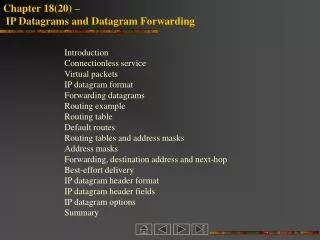
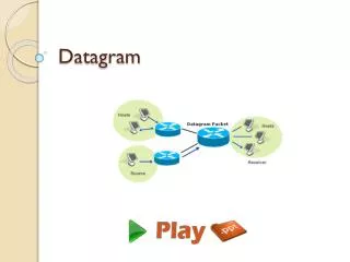
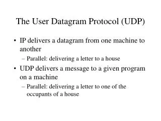
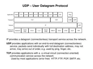
Inside the IP Datagram • Primary function of network layer protocols is to move datagrams through an internetwork connected by routers. • Each packet carries the source IP address and the destination address embedded in the packet header. • As packets cross an internetwork, routers along the way inspect packets and make routing decisions based on the IP address. • There are many fields inside the packet serving specific functions. This section looks at how packets are formed, fragmented, reassembled, and the details of IP packet structure. L. Krist NVCC
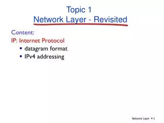
Sending IP Datagrams • Building a datagram to transmit on the wire requires: • IP addresses of source and destination • Hardware addresses of source and destination • IP addresses are used to identify hosts on a TCP/IP internetwork.(Network Layer) The hardware address is required to get a packet from one IP host to another IP host on a single network. (Data Link Layer). • IP host can compare the destination IP with it’s own local network address. Once it determines the destination is a remote network, it must determine the hardware address of the appropriate router for the packet. L. Krist NVCC
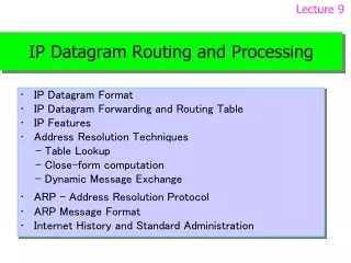
Route Resolution Process Source MAC:0x00001B333444Destination MAC: 0x00001CAB111Source IP: 10.1.0.20Destination IP: 10.2.0.2 Network 10.2.0.0 Network 10.1.0.0 Source MAC: 0x00001CAB222Destination MAC: 0x00001B555666Source IP: 10.1.0.20Destination IP: 10.2.0.2 1 2 Server 1 IP Address 10.2.0.2Mask: 255.255.0.0MAC: 0x00001B555666 Client A IP Address 10.1.0.20Mask: 255.255.0.0MAC: 0x00001B333444 Interface 2 IP Address 10.2.0.33Mask: 255.255.0.0MAC: 0x00001CAB222 Interface 1 IP Address 10.1.0.33Mask: 255.255.0.0MAC: 0x00001CAB111 Client A sends datagram to the server. IP networks are different. Client A must go through the router to the server. Source sends a special datagram called an ARP to learn the address of the server. Once known, it is embedded in the packet and sent on it’s way. L. Krist NVCC
ARP (Address Resolution Protocol) • ARP is an IP layer protocol that obtains the MAC address of a host, then creates a database that maps the MAC address to the IP address. “Will the computer with IP address 123.4.5.6 please send me its MAC address?” • As a computer learns MAC-to-IP address mappings, it stores them in an ARP table. The next time it needs a MAC address, it consults the ARP cache first. The ARP table learns dynamically and times out entries. Entries can be manually entered as well. L. Krist NVCC
ARP Table Entries As hosts monitor the network, they can learn the IPs and MAC addresses of all the traffic that passes by them on their local segment. This helps them populate their ARP tables. L. Krist NVCC
ARP/RARP Message Structure Operation field value indicates what kind of message this is The opposite of ARP is RARP. RARP allows the device to make a request to learn its IP address. Devices using RARP require that a RARP server be present on the network to answer RARP requests. This has been replaced by DHCP as well. L. Krist NVCC
Proxy ARP Request ARP requests are broadcast packets. Routers do not forward broadcasts. Packets must have an IP-MAC pair of addresses. If the destination is not on the local segment, something must be done. If the destination IP address in the ARP request is on a different network, then the router can respond and put the MAC address of it’s LAN interface in the packet. (The router gives a proxy address.) The other option is to set a default gateway on the host. L. Krist NVCC
Default Gateway The default gateway is the provided address that the host should use if the IP addresses of source and destination on are different networks. L. Krist NVCC
Internet Protocol OSI Protocol Implementation DARPA Terminal Emulation Electronic Mail Client Server Network Mgmt File Transfer File Transfer PROTOCOL COMPARISON Application File Transfer Protocol (FTP) RFC 559 Presentation Simple Network Management Protocol (SNMP) RFC 1157 Simple Mail Transfer Protocol (SMTP) RFC 821 Network File System Protocol (NFS) RFC 1024, 1057 and 1094 Trivial File Transfer Protocol (TFTP) RFC 783 TELNET Protocol RFC 854 Process Session Transmission Control Protocol (TCP) RFC 793 User Datagram Protocol (UDP) RFC 768 Host-to-Host Transport Internet Control Message Protocol (ICMP) RFC 792 Address Resolution Protocols ARP: RFC 826 RARP: RFC 903 Internet Protocol (IP) RFC 791 Internet Network Network Interface Cards Data Link Ethernet Token Ring Starlan Arcnet FDDI SMDS Network Interface Transmission Mode Physical TP STP FO Satellite Microwave, etc L. Krist NVCC
TCP/IP Protocol Suite DNS TFTP SNMP HTTP FTP Telnet SNMP Rlogin Ping Traceroute SERVICES Transmission Control Protocol User Datagram Protocol TRANSPORT Internet Group Management Protocol Internet Control Message Protocol NETWORK Internet Protocol Reverse Address Resolution Protocol Address Resolution Protocol LINK Interface Hardware L. Krist NVCC TCP/IP Protocol Suite
TCP/IP Protocols • Transmission Control Protocol. TCP provides application programs access to the network using a reliable, connection-oriented transport layer service. • User Datagram Protocol. UDP provides unreliable, connection-less delivery service using the IP protocol to transport messages between machines. It adds the ability to distinguish among multiple destinations on a single host computer. • Internet Protocol. IP receives datagrams from the upper-layer software and transmits it to the destination host based upon a best effort, connection-less delivery service. • Internet Control Message Protocol. ICMP allows internet routers to transmit error messages and test messages. • Internet Group Message Protocol. IGMP is used with multicast to send UDP datagrams to multiple hosts. • Address Resolution Protocol. ARP translates between the 32 bit IP address and a 48 bit LAN address. • Reverse Address Resolution Protocol. RARP translates between the 48 bit LAN address and the 32 bit IP address. L. Krist NVCC
IP Encapsulation DATA DATA IP Header IP DATAGRAM DATA 0800 Identifies protocol type in a SNAP-PDU Protocol Header Organiz Ident SNAP-PDU IP Datagram Identifies a Private Network Layer Protocol TCP/IP is considered a Privte Protocol SSAP x "AA" DSAP x "AA" LLC-PDU SNAP - PDU Control Identifies the IEEE SNAP Protocol IEEE 802.3 CSMA/CD DSAP x "AA" Organiz Ident SSAP x "AA" Protocol Header Preamble Control DATA DA FCS Length SA 802.2 LLC 802.2 SNAP 802.3 CSMA/CD ARP Request/Reply ARP 0806 RARP Request/Reply 8035 RARP L. Krist NVCC NOTE: ARP/RARP is carried in the physical frame and not encapsulated in IP
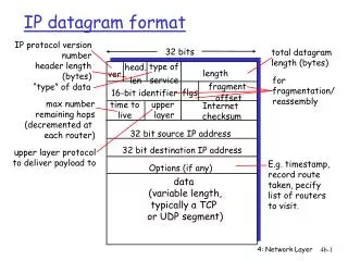
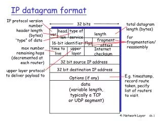
IP Datagram Fields 0 15 16 31 HLEN Total Length TOS VERS 4 bits 4 bits 8 bits 16 bits Fragment Offset Identification Flags 13 bits 16 bits 3 bits TTL Protocol Checksum 20 bytes 8 bits 16 bits 8 bits 60 bytes Source IP Address 32 bits Destination IP Address 32 bits IP Options(if any) <= 40 bytes 32 bits IP Datagram Data 32 bits ETHERNET FIELD TYPE DESTINATION ADDRESS SOURCE ADDRESS IP DATA PREAMBLE FCS 0-1500 2 4 8 6 6 Maximum Transmission Unit MTU (bytes) Network Hyperchannel 65335 16 Mb/s Token Ring 17914 4 Mb/s Token Ring 4464 FDDI 4352 Ethernet 1500 IEEE 802.3/802.2 1492 X.25 576 L. Krist NVCC
IP Datagram Fields Total Length HLEN TOS VERS 4 bits 4 bits 8 bits 16 bits Flags Fragment Offset Identification D M 0 • VER. The current version of IP is 4. • HLEN. The header length is the number of 32-bit words in the header including the options. The normal value will be 5 which is the shortest header allowed. • Protocol. Defines which protocol is coming up next – for IP it is typically TCP or UDP, or ICMP. • Total Length. This is the total length of the IP datagram in bytes. The field is 16 bits, therefore, the maximum size of an IP datagram will be 65536 bytes. • IP will normally fragment this datagram. • Fragment size will depend upon the link layer MTU. 13 bits 16 bits F F TTL Protocol Checksum 20 bytes 60 bytes 8 bits 16 bits 8 bits Source IP Address 32 bits Destination IP Address 32 bits IP Options(if any) <= 40 bytes IP Datagram Data L. Krist NVCC
IP Datagram Fields HLEN Total Length TOS VERS 4 bits 4 bits 8 bits 16 bits Flags Fragment Offset Identification D M 0 13 bits 16 bits F F TTL Protocol Checksum 8 bits 16 bits 8 bits Source IP Address • Checksum. This is a Cyclic Redundancy Check that is calculated for the IP header only and not the data. • For purposes of calculation the Header Checksum field is assumed to contain zero. • The higher level protocols, TCP, UDP, ICMP and IGMP must add their own checksum. The checksum is calculated at each router. • IP Addresses. Each IP datagram contains a 32 bit Source IP Address and a Destination IP Address. • These field values will never change even though the datagram may be routed through many intermediate gateways. • IP Options. This field is a variable length list of optional information. • It can include such things as security and handling restrictions, • a route record, a timestamp for the IP address, • a list of IP addresses that must be traversed (loose source routing), and • a list of IP addresses that can only be traversed (strict source routing) . • Pad bytes with a value of 0 are added if necessary to assure a header with a multiple of 32 bits. The option field is rarely used. 32 bits Destination IP Address 32 bits IP Options(if any) IP Datagram Data L. Krist NVCC
Fragmentation 0 15 16 31 Total Length HLEN TOS VERS 16 bits 4 bits 4 bits 8 bits Flags Fragment Offset Identification TTL Protocol Checksum 20 bytes 8 bits 16 bits 8 bits 60 bytes Source IP Address • All networks have a Maximum Transmission Unit (MTU) size. • All hosts and routers are required to handle datagrams of at least 576 octets. • IP contains procedures for fragmenting large datagrams into smaller datagrams. • The transmitting host or intermediate routers may fragment a datagram. • The receiving host has responsibility for reassembly. • Fragments containing matching Identification, Source IP, Destination IP and Protocol fields belong together. • The Identification, Flags and Fragmentation Offset fields enable datagrams to be fragmented and reassembled. 32 bits Destination IP Address 32 bits IP Options(if any) <= 40 bytes 32 bits IP Datagram Data 32 bits MTU = 1500 MTU = 512 MTU = 1500 L. Krist NVCC
Fragmentation 0 15 16 31 Total Length HLEN VERS TOS 16 bits 4 bits 4 bits 8 bits Flags Fragment Offset Identification TTL Protocol Checksum 20 bytes 8 bits 16 bits 8 bits 60 bytes Source IP Address 32 bits Destination IP Address 32 bits • Identification. This field uniquely identifies each datagram sent by the host. It is normally incremented by one each time a datagram is sent. • Flags. The low order two bits control fragmentation. • DF = 1 indicates Do Not Fragment while • DF = 0 indicates this datagram may be fragmented. • MF = 1 indicates to the receiver that more fragments are to follow while • MF = 0 indicates this is the last fragment. • Fragment Offset. This field specifies the offset in the original datagram of the data being carried in this fragment measured in bytes starting at offset zero, • This field contains the number of Fragment Blocks (8-octet blocks). IP Options(if any) <= 40 bytes 32 bits IP Datagram Data 32 bits MTU = 1500 MTU = 512 MTU = 1500 L. Krist NVCC
Fragmentation 0 15 16 31 Total Length HLEN TOS VERS 16 bits 4 bits 4 bits 8 bits Flags Fragment Offset Identification TTL Protocol Checksum 20 bytes 8 bits 16 bits 8 bits 60 bytes Source IP Address 32 bits Destination IP Address 32 bits IP Options(if any) <= 40 bytes 32 bits IP Datagram Data 32 bits MTU = 1500 MTU = 512 MTU = 1500 Fragment 1 TL 512 ID 26313 DF 0 MF 1 OS 0 TL 1500 ID 26313 DF 0 MF 0 OS 0 Router Fragmentation Fragment 2 TL 512 ID 26313 DF 0 MF 1 OS 64 • Check the Flags field. • If DF = 0 then fragment datagram into pieces based upon next MTU. • If DF = 1 discard datagram and generate destination unreachable ICMP. • Duplicate the IP header on each fragment with the following exceptions: • Change the Length field to equal the fragment length. • Set intermediate MF = 1 except set the final MF = 0. • Set the Fragment Offset field to indicate the position of this fragment's data relative to the data in the original datagram. • Calculate a new checksum for this fragment. Fragment 3 TL 480 ID 26313 DF 0 MF 0 OS 128 L. Krist NVCC
Fragmentation Reassembly 0 15 16 31 Total Length HLEN VERS TOS 16 bits 4 bits 4 bits 8 bits Flags Fragment Offset Identification TTL Protocol Checksum 20 bytes 8 bits 16 bits 8 bits 60 bytes • Intermediate IP routers do not perform fragmentation reassembly because they do not know how to the handle the offset(fragments can travel different routes). • The receiving host has responsibility for fragment reassembly. • Fragments with matching Identification, Source IP Address, Destination IP Address and Protocol fields belong together. • The receiving host will normally allocate small incremental buffers to hold incoming fragments. • The receiving host starts a reassembly timer (normally between 60 and 120 seconds). • Upon timer expiration the host discards the received fragments and sends a Time Exceeded ICMP message. Source IP Address 32 bits Destination IP Address 32 bits IP Options(if any) <= 40 bytes 32 bits IP Datagram Data 32 bits L. Krist NVCC
Total Length HLEN TOS VERS 4 bits 4 bits 8 bits 16 bits Flags Fragment Offset Identification D M 0 13 bits 16 bits F F TTL Protocol Checksum 20 bytes 8 bits 16 bits 8 bits 60 bytes Source IP Address 32 bits Destination IP Address 32 bits IP Options(if any) <= 40 bytes IP Datagram Data Type of Service Precedence 000 Routine 001 Priority 010 Immediate 011 Flash 100 Flash Override 101 Critical 110 Internetwork Control 111 Network Control 0 1 2 3 4 5 6 7 PrecedenceType of Service MBZ Type of Service 0000 Default 0001 Min monetary cost 0010 Max reliability 0100 Max throughput 1000 Min delay 1111 Max security Differentiated Services – Uses this field to store service code point that tells router to how to handle this traffic. 0 1 2 3 4 5 6 7 Differentiated ServiceECN CE L. Krist NVCC
Lab Projects • View ARP cache • Start => Run => cmd • Enter arp –a • View route table • Start => Run => cmd • Enter route print • Packet analyzer Ethereal • Arp, ftp, and fragments L. Krist NVCC
Utilities – PING, TRACERT • PING Packet Internetwork Groper – Checks accessibility and round trip time between specific sender and receiver pair of IP addresses. PING uses an ICMP echo and Echo Reply packets. • Traceroute/Tracert – Traces the path from sender to target host. Uses ICMP echo requests and manipulation of TTL field to produce the list of routers along the path. Windows 2000 and later also provide utility PATHPING. L. Krist NVCC
ICMP – Internet Control Message Protocol • ICMP is a Layer 3 protocol • The IP protocol itself is non-reliable/best effort delivery method for network data, reliable delivery services are provided by upper layers. • Best effort delivery methods do not notify the sender if delivery fails, so ICMP was created as a Layer 3 testing mechanism, and as an error reporting protocol for IP. When datagram delivery errors occur, ICMP is used to report these errors back to the sender of the datagram. L. Krist NVCC
Ping and Echo Request/Echo Reply Messages • ICMP can be used to issue an Echo Request message to a particular host. The receiving host will formulate an Echo Reply message back. If the sender receives the reply, it confirms that the destination is reachable. Initiate the process with a ping command. • If a destination is not reachable, then a Destination Unreachable message is sent back. (Type field = 3)The Code value indicates the reason the packet could not be sent. There are a myriad of reason why a destination Is not reachable. • ICMP may issue a Time Exceeded code by reading the TTL value in the IP packet headers. This is also the basis for the traceroute command. L. Krist NVCC
Network Reachability and Error Reporting with ICMP • When a packet cannot reach it’s destination, the last good router will issue an ICMP packet back to the source IP host to notify them the packet was not delivered. • ICMP does not correct problems and is not used by routers to advertise down routes to other routers – only to notify the sending host an error occurred. • If an ICMP packet itself is undeliverable, it will NOT generate another ICMP message, or if could result in congestion. The host may be unreachable, or the network, or the upper layer protocol or the port. L. Krist NVCC
ICMP Packet 0 15 16 31 • ICMP packets contain only three required fields after the IP header: Type, Code and Checksum HLEN Total Length TOS VERS 4 bits 4 bits 8 bits 16 bits Fragment Offset Identification Flags 13 bits 16 bits 3 bits TTL Protocol Checksum 20 bytes 8 bits 16 bits 8 bits 60 bytes Source IP Address 32 bits Destination IP Address 32 bits IP Options(if any) <= 40 bytes 32 bits ICMP Type ICMP Code Checksum IP Datagram Data 32 bits ETHERNET FIELD TYPE DESTINATION ADDRESS SOURCE ADDRESS ICMP IP header PREAMBLE FCS 0-1500 L. Krist NVCC
ICMP Message Types • ICMP packets have a specific format. Each message type has its own characteristics, but all begin with the same 3 fields. This figure shows the message format for Echo Request and Echo Reply Code Values and Descriptions (for Type 3 Messages) L. Krist NVCC
ICMP Control Messages • In contrast to Error messages, Control messages inform hosts of conditions about the network. Examples: • Redirect/Change Requests • Clock synchronization • Transit Time Estimation • Information Request (and Reply) • Address Mask Request • Router Discovery • Router Solicitation • Congestion and Flow Control L. Krist NVCC
Interpreting trace data files L. Krist NVCC