Download
1 / 17
170 likes | 306 Vues
WORKSHOP 14 FULL-VEHICLE ASSEMBLY. Full-Vehicle Assembly.

E N D
WORKSHOP 14 FULL-VEHICLE ASSEMBLY
Full-Vehicle Assembly • This workshop is intended to combine the knowledge you have attained throughout the course to create a full-vehicle assembly. The major steps for this workshop are described, but the exact steps are omitted. If you have questions, please refer to previous sections or ask the instructor. • At this point, you should have the following templates done: • MacPherson suspension (be sure to use the one you created rather than the one in the shared database, because these have topological differences) • Rack and pinion steering • You should also have access to _double_wishbone.tpl and _handling_tire.tpl, which is located in the shared database. • Before you build the assembly, you must create the body. You then attach the front and rear suspensions, together with the steering system, to the body. You also create appropriate communicators. • Add database provided by the instructor to your session • Extract the acar_training_MDr2.zip to you acar folder. • Go to Tools – Database Management – Add to Session • Type Database Alias – acar_training_MDr2 and browse to the acar_training_MDr2.cdb folder.
Full-Vehicle Assembly • Creating the Body • In Template Builder, open the template body_training.tpl, which is in the database you added to the session. This template has one rigid body (ges_chassis) that will act as the chassis. • Creating and testing communicators • Body versus MacPherson suspension (used as front suspension) • Open the MacPherson template you created before. • Use Communicator Info to confirm that the front suspension hooks up to the body. For the MacPherson suspension, you have the following input communicators ci[lr]_strut_to_body mount ci[lr]_subframe_to_body mount ci[lr]_tierod_to_steering mount • For the body, the communicators of interest are strut_to_body and subframe_to_body, which are mount communicators. You must convey to the front suspension what part the upper strut should attach to. In this case it's the body, since that is the only part in the chassis template. • Create a new output communicator in _body_training.tpl of type mount (name it body, assign to it either right or left symmetry), that will match the ci[lr]_strut_to_body, by entering the same matching name. • Edit the communicator, body, to have a matching name for subframe_to_body. • Test the communicators between the body and the MacPherson templates. Remember that you must have the templates open to be able to test them. Use a minor role of any for the body and front for the suspension.
Full-Vehicle Assembly • Body versus steering • Open the steering template. Here you will set up the steering and body template so that they will attach to each other. That is, make sure that the steering-column housing and rack housing are attached to the body. The rack housing should really be attached to a suspension subframe, but since you are not including a subframe, use the body instead. • Display the body template and create an output communicator of type mount, single symmetry, with the name body_single, with a matching name of the corresponding input communicator, named steering_column_to_body, in the steering template. • Modify the same single output communicator to include the matching name rackhousing_to_body. • Test the communicators between the body and the steering. Use a minor role of any for the body, and front for the steering.
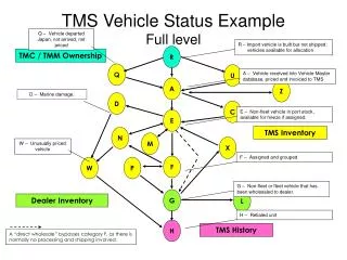
Full-Vehicle Assembly • Body versus double-wishbone suspension (used as rear suspension) In this section, you will set up communicators so that the rear suspension hooks up to the body. For information about this template, look in the online help documentation. • Open the double-wishbone suspension from the Adams/Car shared database. • Select Build - Communicator - Info. • Set Type to Input, set Entity to Many, and then select mount. Select OK. Adams/Car displays a list of all input communicators in the double-wishbone suspension template: Listing of input communicators in '_double_wishbone' ---------------------------------------------------------------- Communicator Name: Class: From Minor Role: Matching Name: ci[lr]_strut_to_body mount inherit strut_to_body ci[lr]_tierod_to_steering mount inherit tierod_to_steering ci[lr]_tripot_to_differential mount inherit tripot_to_differential ci[lr]_uca_to_body mount inherit uca_to_body cis_subframe_to_body mount inherit subframe_to_body '_double_wishbone' contains: 9 input communicators of type 'mount‘ • Perform a communicator test between the body (any) and double-wishbone suspension (rear), and confirm that the strut attaches to the body. This is the same communicator in the body template you created for the front suspension, so you don’t have to create it again. It should pass the information to both the front and the rear mount parts.
Full-Vehicle Assembly • Modify the left/right body communicator, named body, in the body to pass information to the uca_to_body input communicator located in the double-wishbone suspension template. • To keep the wheels going straight, hook up the tie rods to the body, so the wheels won't turn. Create a left/right mount communicator named body_rear. This time, instead of inherit for a minor role, choose rear, and enter tierod_to_steering as a matching name. • Modify the single body output communicator, named body_single, to include the matching name subframe_to_body for the double-wishbone suspension. The previous communicators are pretty straightforward, but let's investigate input communicators ci[lr]_tripot_to_differential in the double-wishbone suspension. • From the Tools menu, select Database Navigator. • At the top of the Database Navigator, select Associativity. • In the Filter text box, enter *tripot*, and then press Enter.
Full-Vehicle Assembly • Double-click _double_wishbone to see the modeling elements that contain the string tripot in their names. You should see, among others: • cil_tripot_to_differential • cir_tripot_to_differential • Highlight either of these, and then, in the right window of the Database Navigator, at the bottom, select Uses. You should see the following: ._double_wishbone.cir_tripot_to_differential.cir_tripot_to_differential = ._double_wishbone.ground.mtr_mount_j_5 (Marker) ._double_wishbone.cir_tripot_to_differential.cir_tripot_to_differential = ._double_wishbone.mtr_tripot_to_differential (Part) ._double_wishbone.cir_tripot_to_differential.cir_tripot_to_differential = ._double_wishbone.mtr_fixed_5 (Fixed Joint) ._double_wishbone.cir_tripot_to_differential.minor_role.minor_role = ._double_wishbone.mtr_tripot_to_differential.minor_role (Variable) • In the Database Navigator, change Associativity to Topology by Parts.
Full-Vehicle Assembly • Select mti-tripot-to-differential, which should show you the following: Part mtl-tripot_to differential is connected to: ground through mtl_fixed_5 (Fixed Joint) gel_tripot through joltra_tripot_to_differential (Translational Joint) Therefore, the tripot_to_differential mount part is connected to ge[lr]_tripot. • Select gel_tripot Part gel-tripot is connected to: mtl_tripot_to_differential through joltra_tripot_to_differential (Translational Joint) gel_drive_shaft through jolcon_drive_sft_int_jt (Convel Joint) • Enter “*” for the filter and select gel_drive_shaft. Part gel_drive_shaft is connected to: gel_tripot through jolcon_drive_sft_int_jt (Convel Joint) gel_spindle through jolcon_drive_sft_otr (Convel Joint) • You can use the Database Navigator again to look at the Associativity of the spindle (toggling Is Used By). Note that the spindle is used by an output communicator: ._double_wishbone.col_suspension_mount.col_suspension_mount = ._double_wishbone.gel_spindle (Part) This is the mount that should connect to the wheel. So, overall, you can see that the tripot_to_differential mount part should normally connect to a powertrain, if you wanted to use one. Because you are not including a powertrain for this exercise, we will ignore this mount part and let it connect to ground. In the Standard Interface, you will then deactivate the driveline so that the vehicle is not locked to ground, too.
Full-Vehicle Assembly • Double –wishbone suspension versus wheels • The double-wishbone suspension must pass the information on the part to which the wheels should attach. You must edit the mount output communicators in the doublewishbone suspension named suspension_mount to include the matching name wheel_to_susp. • Body versus SDI_testrig • To check the test rig, SDI_testrig, select Build -> Communicator -> Info. There is one mount input communicator that expects information from the body, cis_body_subsystem. • Modify cos_body_single in the body template to include the body_subsystem matching name. • Test all the communicators for all the templates that you will use for the full vehicle. NOTE: When testing these communicators, you must specify what the templates’ minor roles will be when you will build the subsystems. Assign minor roles to templates, as shown next:
Full-Vehicle Assembly Template: Minor role: .__MDI_SDI_TESTRIG any ._Handling_Tire front ._Handling_Tire rear ._body_training any ._double_wishbone rear ._steer_final front ._macpherson front The following is communicator information for the mount and location classes in the templates after modifications in this workshop (one example; other variations will work, too, depending on implementation): Listing of input communicators in '_handling_tire' ci[lr]_suspension_mount mount inherit suspension_mount ci[lr]_suspension_upright mount inherit suspension_upright ci[lr]_wheel_center location inherit wheel_center Listing of output communicators in '_handling_tire' co[lr]_rotor_to_wheel mount inherit rotor_to_wheel
Full-Vehicle Assembly Listing of input communicators in '_macpherson_final' ci[lr] _strut_to_body mount inherit strut_to_body ci[lr]_subframe_to_body mount inherit subframe_to_body ci[lr]_tierod_to_steering mount inherit tierod_to_steering Listing of output communicators in '_macpherson_final' co[lr]_wheel_center location inherit wheel_center co[lr]_suspension_mount mount inherit suspension_mount, wheel_to_susp co[lr]_suspension_upright mount inherit suspension_upright Listing of input communicators in '_double_wishbone' ci[lr]_arb_pickup location inherit arb_pickup ci[lr]_strut_to_body mount inherit strut_to_body ci[lr]_tierod_to_steering mount inherit tierod_to_steering ci[lr]_tripot_to_differential mount inherit tripot_to_differential ci[lr]_uca_to_body mount inherit uca_to_body cis_subframe_to_body mount inherit subframe_to_body
Full-Vehicle Assembly Listing of output communicators in '_double_wishbone' co[lr]_tripot_to_differential location inherit tripot_to_differential co[lr]_wheel_center location inherit wheel_center co[lr]_arb_bushing_mount mount inherit arb_bushing_mount co[lr]_droplink_to_suspension mount inherit droplink_to_suspension co[lr]_suspension_mount mount inherit suspension_mount, wheel_to_susp co[lr]_suspension_upright mount inherit suspension_upright cos_engine_to_subframe mount inherit engine_to_subframe cos_rack_housing_to_suspension_subframe mount inherit rack_housing_to_suspension_subframe Listing of input communicators in '_steer_final' cis_rackhousing_to_body mount inherit rackhousing_to_body cis_steering_column_to_body mount inherit steering_column_to_body ci[lr]_tierod_to_steering mount inherit tierod_to_steering ci[lr]_tripot_to_differential mount inherit tripot_to_differential ci[lr]_uca_to_body mount inherit uca_to_body cis_subframe_to_body mount inherit subframe_to_body Listing of output communicators in '_steer_final' co[lr]_tierod_to_steering mount inherit tierod_to_steering
Full-Vehicle Assembly Listing of input communicators in '_body_final' 0 input communicators of type 'location' 0 input communicators of type 'mount‘ Listing of output communicators in '_body_final' co[lr]_body mount inherit strut_to_body, subframe_to_body, uca_to_body co[lr]_body_rear mount rear tierod_to_steering cos_body_single mount inherit steering_column_to_body, rackhousing_to_body, subframe_to_body, body_subsystem Listing of input communicators in '_MDI_SDI_TESTRIG' ci[lr]_front_suspension_mount mount front suspension_mount ci[lr]_rear_suspension_mount mount rear suspension_mount cis_body_subsystem mount inherit body_subsystem ci[lr]_wheel_center_front location front wheel_center ci[lr]_wheel_center_front location rear wheel_center Listing of output communicators in '_MDI_SDI_TESTRIG' cos_std_tire_ref location any std_tire_ref
Full-Vehicle Assembly • Save all your templates • Create new subsystems for all your templates • Create a new full vehicle assembly with the subsystems you just created.Confirm that none of the critical communicators appear in the warning message about unmatched communicators. Otherwise, close the assembly and return to Template Builder to make the necessary changes. Adams/Car displays the following message about unassigned communicators: testrig.cis_rotation_diff testrig.cis_clutch_diff testrig.cis_engine_rpm testrig.cis_max_gears testrig.cis_diff_ratio testrig.cis_max_throttle testrig.cis_max_brake_value testrig.cis_max_engine_speed testrig.cis_min_engine_speed testrig.cis_transmission_spline testrig.cis_transmission_input_omega testrig.cis_clutch_displacement_ic dwb.ci[lr]_ARB_pickup dwb.ci[lr]_tripot_to_differential (attached to ground) Note that ci[l,r]_tripot_to_differential has attached to ground. You will deactivate the driveline so that it is not used, since you have not included a powertrain, and the vehicle will not be attached to ground.
Full-Vehicle Assembly • Adjust the different subsystems so they appear in the right location relative to each other. Shift the front and the rear suspensions by this amount: • Front suspension aft 250 mm up 230 mm • Rear suspension aft 2800 mm up 37.30 mm • Steering aft 250 mm up 230 mm • From the View menu, select Subsystem, and then select the double-wishbone suspension in your assembly. • From the Adjust menu, select Driveline Activity, and then set Current Mode to Inactive. This turns off the driveline in the rear suspension, which removes the connection of the vehicle to ground. • Select View -> Assembly. • Define a preload: • Right-click either of the front springs, and then select Modify. • Set Installed Length to 135. • Select OK. • Change the front dampers: • Right-click either of the front dampers, and then select Modify. • Set the damper to <acar_shared>/dampers.tbl/mdi_shk0001.dpr. • Select OK.
Full-Vehicle Assembly • Run any full-vehicle open-loop steering analysis. In the open-loop steering analyses, because the assembly has no powertrain, there will be no power to the wheels. You can, however, run these events with initial velocity.