Download
1 / 55
700 likes | 813 Vues
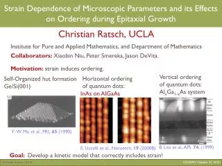
Presentation on Antenna and its parameters ( Antenna Basics). An antenna is a way of converting the guided waves present in a waveguide, feeder cable or transmission line into radiating waves travelling in free space, or vice versa. Only accelerating charges produce radiation. References.

E N D
An antenna is a way of converting the guided waves present in a waveguide, feeder cable or transmission line into radiating waves travelling in free space, or vice versa.
Only accelerating charges produce radiation. References
Two fields regions: Near field or Fresnel region: The region within the radius of the smallest sphere which completely encloses the antenna is called Fresnel region. In sitting an antenna ,it’s crucial to keep objects out of the near field region to avoid coupling the currents in the antenna with objects. Far Field or Fraunhofer region: The region beyond Fresnel region is called Fraunhofer region
Antenna parameters are: 1.Radiation Pattern 2.Directivity 3.Radiation Resistance and Efficiency 4.Power Gain 5.Bandwidth 6.Reciprocity 7.Effective Aperture 8.Beamwidth and Directivity 9.The Friis Formula: Antennas in Free Space 10.Polarisation Matching
The radiation pattern of an antenna is a plot of the far-field radiation from the antenna. More specifically, it is a plot of the power radiated from an antenna per unit solid angle, or its radiation intensity U [watts per unit solid angle. This is arrived at by simply multiplying the power density at a given distance by the square of the distance r, where the power density S [watts per square meter is given by the magnitude of the time-averaged Poynting vector: U=r^²S
Antenna parameters are: 1.Radiation Pattern 2.Directivity 3.Radiation Resistance and Efficiency 4.Power Gain 5.Bandwidth 6.Reciprocity 7.Effective Aperture 8.Beamwidth and Directivity 9.The Friis Formula: Antennas in Free Space 10.Polarisation Matching
The directivity D of an antenna, a function of direction is defined by the ratio of radiation intensity of antenna in direction to the mean radiation intensity in all directions.
Antenna parameters are: 1.Radiation Pattern 2.Directivity 3.Radiation Resistance and Efficiency 4.Power Gain 5.Bandwidth 6.Reciprocity 7.Effective Aperture 8.Beamwidth and Directivity 9.The Friis Formula: Antennas in Free Space 10.Polarisation Matching
The resistive part of the antenna impedance is split into two parts, a radiation resistance Rr and a loss resistance Rl. The power dissipated in the radiation resistance is the power actually radiated by the antenna, and the loss resistance is power lost within the antenna itself. This may be due to losses in either the conducting or the dielectric parts of the antenna. Radiation efficiency e of the antenna as e is the ratio of power radiated to the power accepted by antenna antenna with high radiation efficiency therefore has high associated radiation resistance compared with the losses. The antenna is said to be resonant if its input reactance Xa =0.
Antenna parameters are: 1.Radiation Pattern 2.Directivity 3.Radiation Resistance and Efficiency 4.Power Gain 5.Bandwidth 6.Reciprocity 7.Effective Aperture 8.Beamwidth and Directivity 9.The Friis Formula: Antennas in Free Space 10.Polarisation Matching
The power gain G, or simply the gain, of an antenna is the ratio of its radiation intensity to that of an isotropic antenna radiating the same total power as accepted by the real antenna. When antenna manufacturers specify simply the gain of an antenna they are usually referring to the maximum value of G.
Antenna parameters are: 1.Radiation Pattern 2.Directivity 3.Radiation Resistance and Efficiency 4.Power Gain 5.Bandwidth 6.Reciprocity 7.Effective Aperture 8.Beamwidth and Directivity 9.The Friis Formula: Antennas in Free Space 10.Polarisation Matching
The bandwidth of an antenna expresses its ability to operate over a wide frequency range. It is often defined as the range over which the power gain is maintained to within 3dB of its maximum value, or the range over which the VSWR is no greater than 2:1, whichever is smaller. The bandwidth is usually given as a percentage of the nominal operating frequency. The radiation pattern of an antenna may change dramatically outside its specified operating bandwidth.
Antenna parameters are: 1.Radiation Pattern 2.Directivity 3.Radiation Resistance and Efficiency 4.Power Gain 5.Bandwidth 6.Reciprocity 7.Effective Aperture 8.Beamwidth and Directivity 9.The Friis Formula: Antennas in Free Space 10.Polarisation Matching
Reciprocity theorem: If a voltage is applied to the terminals of an antenna A and the current measured at the terminals of another antenna B then an equal current will be obtained at the terminals of antenna A if the same voltage is applied to the terminals of antenna B.
Antenna parameters are: 1.Radiation Pattern 2.Directivity 3.Radiation Resistance and Efficiency 4.Power Gain 5.Bandwidth 6.Reciprocity 7.Effective Aperture 8.Beamwidth and Directivity 9.The Friis Formula: Antennas in Free Space 10.Polarisation Matching
Effective Aperture If an antenna is used to receive a wave with a power density S [W m2], it will produce a power in its terminating impedance (usually a receiver input impedance) of Pr watts. The constant of proportionality between Pr and S is Ae, the effective aperture of the antenna in square metres: Pr = AeS For some antennas, such as horn or dish antennas, the aperture has an obvious physical interpretation, being almost the same as the physical area of the antenna, but the concept is just as valid for all antennas. The effective aperture may often be very much larger than the physical area, especially in the case of wire antennas. Note, however, that the effective aperture will reduce as the efficiency of an antenna decreases. The antenna gain G is related to the effective aperture as follows G=4pi/ (lamda)2Ae
Antenna parameters are: 1.Radiation Pattern 2.Directivity 3.Radiation Resistance and Efficiency 4.Power Gain 5.Bandwidth 6.Reciprocity 7.Effective Aperture 8.Beamwidth and Directivity 9.The Friis Formula: Antennas in Free Space 10.Polarisation Matching
The directivity of an antenna increases as its beam width is made smaller, as the energy radiated is concentrated into a smaller solid angle
Antenna parameters are: 1.Radiation Pattern 2.Directivity 3.Radiation Resistance and Efficiency 4.Power Gain 5.Bandwidth 6.Reciprocity 7.Effective Aperture 8.Beamwidth and Directivity 9.The Friis Formula: Antennas in Free Space 10.Polarisation Matching
Antenna parameters are: 1.Radiation Pattern 2.Directivity 3.Radiation Resistance and Efficiency 4.Power Gain 5.Bandwidth 6.Reciprocity 7.Effective Aperture 8.Beamwidth and Directivity 9.The Friis Formula: Antennas in Free Space 10.Polarisation Matching
The polarization mismatch loss is the ratio between the power received by the antenna and the power which would be received by an antenna perfectly matched to the incident wave
Direction of propagation of wave Polarization • Polarization is a characteristic of all transverse waves. • Oscillation which take places in a transverse wave in many different directions is said to be unpolarized. • In an unpolarized transverse wave oscillations may take place in any direction at right angles to the direction in which the wave travels.
Direction of oscillation Direction of travel of wave Linear Polarization • If the oscillation does take place in only one direction then the wave is said to be linearly polarized (or plane polarized) in that direction.
Polarization of Electromagnetic Waves • Any electromagnetic wave consists of an electric field component and a magnetic field component. • The electric field component is used to define the plane of polarization because many common electromagnetic-wave detectors respond to the electric forces on electrons in materials, not the magnetic forces.
Polarization by Selective Absorption • Polarization of light by selective absorption is analogous to that shown in the diagrams.
Polarizing axis Polaroid • A Polaroid filter transmits 80% or more of the intensity of a wave that is polarized parallel to a certain axis in the material, called the polarizing axis. • Polaroid is made from long chain molecules oriented with their axis perpendicular to the polarizing axis; these molecules preferentially absorb light that is polarized along their length.
Explanation of Polarization at the Molecular Level (1) • An electric field E that oscillates parallel to the long molecules can set electrons into motion along the molecules, thus doing work on them and transferring energy. Hence, E gets absorbed.
Explanation of Polarization at the Molecular Level (2) • An electric field E perpendicular to the long molecules does not have this possibility of doing work and transferring its energy, and so passes through freely. • When we speak of the axis of a Polaroid, we mean the direction which E is passed, so a polarizing axis is perpendicular to the long molecules.
Intensity of Light transmitted through a Polarizer (1) • An ideal polarizer passes 100% of the incident light that is polarized in the direction of the polarizing axis but completely blocks all light that is polarized perpendicular to this axis. • When unpolarized light is incident on an ideal polarizer, the intensity of the transmitted light is exactly half that of the incident unpolarized light, no matter how the polarizing axis is oriented.
θ Transmitted wave Incident beam of Amplitude Vertical Polaroid Intensity of Light transmitted through a Polarizer (2) • If a beam of plane-polarized light strikes a polarizer whose axis is at an angle of θ to the incident polarization direction, the beam will energy plane-polarized parallel to the polarizing axis and its amplitude will be reduced by cos θ.
Intensity of Light transmitted through a Polarizer (3) • A Polaroid passes only that component of polarization that is parallel to its axis. • As the intensity of a light beam is proportional to the square of the amplitude, and Hence the intensity of a plane-polarized beam transmitted by a polarizer is
Polarization by Reflection • Unpolarized light can be polarized, either partially or completely, by reflection. • The amount of polarization in the reflected beam depends on the angle of incidence.
Incident ray Reflected ray Brewster’s law • It is found that experimentally when the reflected ray is perpendicular to the refracted ray, the reflected light will be completely plane-polarized.
Polarizing angle (Brewster’s angle) • The angle of incidence at which the reflected light is completely plane-polarized is called the polarizing angle (or Brewster’s angle). By Snell’s law, and Since Then we get
y Gas molecule z O x Unpolarized sunlight Light scattered at right angles is plane-polarized Polarization by Scattering (1) • When a light wave passes through a gas, it will be absorbed and then re-radiated in a variety of directions. This process is called scattering.
Polarization by Scattering (2) • Consider a gas molecule at point O. The electric field in the beam of sunlight sets the electric charges in the molecule into vibration. • Since light is a transverse wave, the direction of the electric field in any component of the sunlight lies in the yz-plane, and the motion of charges take place in this plane. • There is no electric field, and hence no motion of charge in the x-direction.
Polarization by Scattering (3) • The molecule reemits the light because the charges are oscillating. But an oscillating charge does not radiate in the direction of its oscillation so it does not send any light to the observer directly below it. • Therefore, an observer viewing at right angles to the direction of the sunlight will see plane-polarized light.
Polarization by Refraction • When an incident unpolarized ray enters some crystals it will be split into two rays called ordinary and extraordinary rays, which are plane-polarized in directions at right angles to each other.
Double Refraction • When light is refracted into two rays each polarized with the vibration directions oriented at right angles to one another, and traveling at different velocities. This phenomenon is termed "double" or "bi" refraction.
Applications of Polarizations (1) • Polaroid sunglasses • The glare from reflecting surfaces can be diminished with the use of Polaroid sunglasses. • The polarization axes of the lens are vertical, as most glare reflects from horizontal surfaces.
Applications of Polarization (2) • Stress Analysis • Fringes may be seen in the parts of a transparent block under stress, viewing through the analyzer. • The pattern of the fringes varies with the stress.
Applications of Polarization (3) • Liquid Crystal Display (LCD)
Applications of Polarization (4) • VHF and UHF antennas (aerial) • Radio waves can be detected either through their E-field or their B-field. • Stations transmitted radio waves which are plane-polarized.
Applications of Polarization (5) • Electric field of EM wave produces a current in an antenna consisting of straight wire or rods.
Applications of Polarization(6) • Changing magnetic field induces an emf and current in a loop antenna.
Blue Sky • The blue color of the sky is caused by the scattering of sunlight off the molecules of the atmosphere. This scattering, called Rayleighscattering, is more effective at short wavelengths
Sunset • As incoming sunlight passes through a more dense atmosphere, shorter wavelengths of light (violet and blue) are efficiently scattered away by particles suspended in the atmosphere. This allows predominantly yellow and red wavelengths of light to reach the observer's eyes, producing a yellowish-red sunset.