Download
1 / 18
180 likes | 184 Vues
Motors and Position Determination. Controlling Position. Feedback is used to control position. Measure the position, subtract a function of it from the desired position and then use this resulting signal to drive the system towards the desired position. This is negative feedback.

E N D
Controlling Position • Feedback is used to control position. • Measure the position, subtract a function of it from the desired position and then use this resulting signal to drive the system towards the desired position. This is negative feedback. • The natural frequencies of the feedback system are the “zeros” of 1 + G(s)H(s). • The total system is unstable if these “zeros” are in the right half plane (RHP). With 180 degrees phase shift, “negative” feedback becomes “positive” feedback. • So we want these “zeros” to be in the left half plane (LHP). • Putting an integrator into H(s) drives steady state error to zero. • But high order systems are more likely to have RHP zeros. • Time delay and high gain lead to RHP zeros.
Servos • We can control parts of the servo, but the system dynamics is often a part we can’t control. • The system dynamics results from masses. springs, losses, etc. • Likely, we will implement servos as digital systems. • Digital systems are more flexible to design. • They are more repeatable; they are not subject to gain drift. • We can use as many bits as we like so we can keep the computation noise small. • Digital systems can have significant delays. • These delays are sometimes fixed, but are sometimes stochastic.
Analog Position Measurements Two sinusoidal potentiometers are used. V1 = V0 cos (theta) V2 = V0 sin (theta) This can also be done magnetically. This is called a resolver and requires a complex analog signal detection. The computation can be done with either analog or digital circuitry. Voltage is proportional to position. A linear or rotary potentiometer can be used. Accuracy is limited to that of the potentiometer and the noise of the power supply voltage.
Digital Position Measurement • Sense light transmission to determine position. • Typically through a transparent sector • Gives a reading over a range of positions. • Depends on extent of transparent sector. • We may need a lot of sensors to determine multiple positions.
Digital Absolute Position • Typically, this is used for relatively low resolutions.
Two-Phase Encoder • Two Source – Sensor Sets • Their position is offset by half the sector width. • This example has 30 degree sectors • and 15 degree resolution.
Use of Two-Phase Encoder • This circuit generates: • An Up/Down signal depending on whether the motion is clockwise (CW) or counterclockwise (CCW). • A clk signal which rising edge is to operate the counter.
Waveforms • A and B are signals derived from sensors. • Rotating one way, the rising edge of clk is when U/D is high. • Rotating the other way, the rising edge of clk is when U/D is low.
Another Way of Making an Encoder • Use two sensors like the two-phase encoder but use only one ring and displace the sensors by ½ band. • Add another ring and a sensor to sense the “home” position.
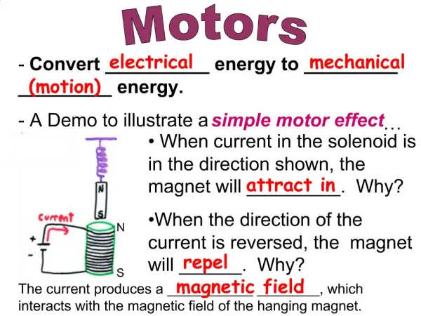
Motors • Simple servomechanisms are made with DC motors. • DC motor model is very simple: • It consists of a resistor in series with a voltage source. • The voltage source is proportional to the rotational speed. • The mechanical system (controlled system) determines the speed as influenced by the torque.
Permanent Magnet DC Motors • They are very commonly used. • The ‘Back Voltage’ is proportional to speed. • The torque is proportional to the current. • Servo Strategy: • Command torque by setting current. • Measure the speed. • Running open loop: • There is a ‘zero torque’ speed. • Torque is proportional to the difference from that speed.
Stepper Motors • Digital Motors • Two ‘stacks’ (phases) • Usually biased by permanent magnets • Move a discrete distance per ‘step’. • This is an axial view cut through both of two sections.
Stepper Motor Windings • Two distinct ‘phases’ • May be driven as distinct windings. • Or may be driven as ‘bifilar’ windings. • Bifilar is easier but less efficient. Unipolar (Bifilar Winding) Bipolar Winding
Bipolar Winding • Driven by ‘H-bridges’ of transistors • Can put current through windings in either direction. • But note that the upper transistor drive is tricky. • Uses all of the winding.
Bifilar Winding • Driven by four transistors to ground. • Note that the center of the windings is held high. • Transistors are between winding and ground. • NPN bipolar transistors work well. • Transistor drives are easily handled.
Motors Run in Either Direction • Current drive strategy: Bipolar Winding Bifilar Winding
Dynamics are Important • Stepper can hold a certain torque. • Stepper can carry more torque at low speed. • At high speed, torque must be de-rated. • Motors draw CURRENT! Make sure your power supply is adequate by measuring the power supply voltage with a ‘scope. • Use an external supply, not the kit supply. • You don’t want motor drive noise in your digital circuit (or analog circuit). • You need to make sure that devices can handle the current and torque.