Download
1 / 29
290 likes | 297 Vues
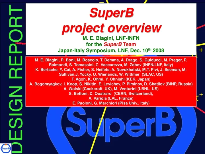
SuperB project overview M. E. Biagini, LNF-INFN for the SuperB Team Japan-Italy Symposium, LNF, Dec. 10 th 2008. M. E. Biagini, R. Boni, M. Boscolo, T. Demma, A. Drago, S. Guiducci, M. Preger, P. Raimondi, S. Tomassini, C. Vaccarezza, M. Zobov (INFN/LNF, Italy)

E N D
SuperB project overviewM. E. Biagini, LNF-INFNfor the SuperBTeamJapan-Italy Symposium, LNF, Dec. 10th 2008 M. E. Biagini, R. Boni, M. Boscolo, T. Demma, A. Drago, S. Guiducci, M. Preger, P. Raimondi, S. Tomassini, C. Vaccarezza, M. Zobov (INFN/LNF, Italy) K. Bertsche, Y. Cai, A. Fisher, S. Heifets, A. Novokhatski, M.T. Pivi, J. Seeman, M. Sullivan,J. Yocky, U. Wienands, W. Wittmer (SLAC, US) T. Agoh, K. Ohmi, Y. Ohnishi (KEK, Japan) A. Bogomyagkov, I. Koop, S. Nikitin, E. Levichev, P. Piminov, D. Shatilov (BINP, Russia) A. Wolski (Cockcroft, UK), M. Venturini (LBNL, US) S. Bettoni, D. Quatraro (CERN, Switzerland), A. Variola (LAL, France) E. Paoloni, G. Marchiori (Pisa Univ., Italy)
Basic concepts (2) SuperB basic concepts • SuperB exploits an alternative approach, with a new IP scheme: • Small beams (ILC-DR like) • very low emittances, ILC-DR R&D • Large Piwinsky angle and “crab waist” with a pair of sextupoles/ring (F = tg(q)sz/sx) • interaction region geometry • Currents comparable to present Factories • lower backgrounds, less HOM and instabilities Requires a lot of fine machine tuning Small collision area: sx/q
Relatively easier to makesmall sxwith respect toshort sz Problem ofparasitic collisionsautomatically solved due to higher crossing angle and smaller horizontal beam size There is no need to increase excessively beam current and to decrease the bunch length: Beam instabilities are less severe Manageable HOM heating No coherent synchrotron radiation of short bunches No excessive power consumption and...
How it works Crab sextupoles OFF: Waist line is orthogonal to the axis of other beam All particles in both beams collide in the minimum by region, with a net luminosity gain Crab sextupoles ON: Waist moves parallel to the axis of other beam: maximum particle density in the overlap between bunches Plots by E. Paoloni
Example of x-y resonance suppression D.Shatilov’s (BINP), ICFA08 Workshop Much higher luminosity! Crab Waist On: 1. large Piwinski angleF >> 1 2.bycomparable withsx/q Typical case (KEKB, DAFNE): 1. low Piwinski angleF< 1 2.bycomparable withsz
Comparison with previous runs • New collision scheme works and CW sextupoles are effective in controlling transverse beam blow-up and increasing luminosity: • Lpeak = 1.6 cm-2s-1 , ∫Lday = 10. pb-1 (KLOE 2003) • Lpeak = 4 cm-2s-1,∫Lday = 12.8 pb-1 (NOW)
Luminosity, crab ON/OFF Luminosity (1028 cm-2s-1) Specific L (1028 cm-2s-1/A2) Luminosity 95 Bunches Specific Luminosity July 2008
Super-B builds on the successes of past accelerators • PEP-II LER stored beam current: 3.2 A in 1722 bunches (4 nsec) @ 3.1 GeV and 23 nm, with little ECI effect on luminosity • Low emittance lattices designed for ILC damping rings, PETRA-3, NSLC-II, and PEP-X (few nm horizontal x few pm vertical) • Very low emittance achieved in an ILC test ring: ATF • Successful crab waist luminosity improvement at DAFNE • Successful crab cavity tests at KEKB at low currents • Spin manipulation tests in Novosibirsk • Efficient spin generation with a high current gun and spin transport to the final focus at the SLC • Successful two beams, asymmetric, interaction regions built by KEKB and PEP-II • Bunch-by-bunch feedbacks work well at 2.7 ns bunch spacing • Continuous injection works with the detector taking data (KEKB and PEP-II)
Comparison of SuperB to Super-KEKB IP beam distributions for KEKB IP beam distributions forSuperB
SuperB main features • Goal: maximize luminosity while keeping wall power low • 2 rings (4x7 GeV) design: flexible but challenging • Ultra low emittance optics: 7x4 pm vertical emittance • Beam currents: comparable to present Factories • Crossing angle and “crab waist” used to maximize luminosity and minimize beam size blow-up • Successfull test at DAFNE !!!!!!!!!!!!!!!!!!! • No “emittance” wigglers used in Phase 1 (save in power) but space is reserved in case needed • Design based on recycling PEP-II hardware (corresponds to a lot of money) • Longitudinal polarization for e- in the HER is included (unique feature): 2 spin rotator sections
Possible scenarios for 1036 (LER/HER) Lower xy Several parameter sets allow to reach1036. No scenario has all parameters pushed to limit J. Seeman, MiniMac, LNF, July 2008
SuperB design challenges • Beam beam • high tune shift • strong-strong simulations for large crossing angle • effect of tolerances and component errors • Low emittance • tolerances • achieving vertical emittance • tuning and preserving • vibrations • IR design • 50 nm IP vertical beam size • QD0 design • luminosity backgrounds • Polarization • impact on lattice • depolarization time • impact on beam-beam • continous injection • Lattice • dynamic aperture with crab sextupoles and spin rotator • choice of good working point Most are being addressed in view of the TDR
Beam-beam simulations • More bb studies were recently performed by D. Shatilov (BINP) with Lifetrack • Explored different y-emittances and bunch lengths in order to decrease the vertical tune shift, in case 0.15 is too difficult to reach • 1036 luminosity can indeed be achieved with reduced xyand relaxed ey and sz: this means shorter beam tails, longer lifetime, at the price of doubling the currents
Beam tails, ey growth and lifetime Nominal 4 ey 2 sz 2 ey + Ösz Optimal case 1036 with 2*Nbunches ey/ey0 t (min) 2.1 50 1.1 5 1.05 300 1.04 100 D. Shatilov, BINP
Final Focus design • FF design complies all the requirements in terms of high order aberrations correction (to be checked with errors and beam-beam simulation) • Crab sextupoles are included in the design • In each half IR two couples of non interleaved sextupoles (H,V), at –I phase, provide correction of first order horizontal and vertical chromaticity • Two additional (H-V) sextupoles at the IP phase cancel the 3rd order chromaticity providing an excellent bandwidth.Since they are placed at a minimum betas location, they should not affect dynamic aperture. • Two octupoles on each side of the IP are used to correct third order aberrations
Final Focus optical functions (Öb) Crab sextupoles LER:bx* = 35 mm, by* = 220 m HER: bx* = 20 mm, by* = 390 m
IR layout, siam twins QD0 (R&D) M.Sullivan (SLAC) • QD0 is common to HER and LER, with axis displaced toward incoming beams to reduce synchrotron radiation fan on SVT • Dipolar component due to off-axis QD0 induces, as in all crossing angle geometries, an over-bending of low energy out coming particles eventually hitting the pipe or detector • New QD0 design based on SC “helical-type” windings S. Bettoni (CERN), E. Paoloni (Pisa)
QD0 windings S. Bettoni (CERN), E. Paoloni (Pisa)
Dual bore pm QD0 (under study) Gives 70% higher field, but worst field quality K. Bertche (SLAC)
Lattice layout: PEP-II magnets reuse Total length 1800 m 20 m 280 m Dipoles Available Needed Quads Sexts All PEP-II magnets can be used, dimensions and fields are in range RF requirements are met by the present PEP-II RF system
Low emittance tuning (1) • VERY important in SuperB, since design ey is 7 and 4 pm • Contributions to ey come mainly from: • tilts in quadrupoles • misaligned sextupoles • vertical dispersion • beam coupling • IBS • e- cloud • trickle injection ? • beam instabilities? • Computer modeling as well as diagnostics will help in achieving and maintaining ey • This work started in collaboration with Cockcroft Inst., and we also profit of work performed for, and experience at, ATF, SLS, CESR-TA and ILC-DR
Low emittance tuning Comparison of achieved beam emittances Comparison of rings with similar beam energy and ATF, SLS (* achieved)
Vertical emittance after orbit and coupling correction PRELIMINARY ! WORK IN PROGRESS There is a queue for ey > 10 pm
Polarization IP • Polarization of one beam is included in SuperB (unique feature) • Either energy beam could be the polarized one • The LER would be less expensive, the HER easier • HER was chosen • Longitudinal polarization times and short beam lifetimes indicate a need to inject vertically polarized electrons. • The plan is to use a polarized e- source similar to the SLAC SLC source. • There are several possible IP spin rotators: • Solenoidslook better at present (vertical bends give unwanted vertical emittance growth) • Expected longitudinal polarization at IP ~ 87%(inj) x 97%(ring) =85%(effective) • Polarization section implementation in HER lattice done Half IR with spin rotator (Wienands, Wittmer)
Depolarization time 3π/2 3π/2 I.P. π/8 π/8 π/8 π/8 π/8 π/8 π/8 π/8 6 7 5 8 4 9 3 2 1 Polarization insertion scheme of 8 solenoids with the Central Arc bend of 2×5.7×3°. Between the solenoids in each group from the left and from the right of the "Central Arc" bends are placed 5 quadrupoles. Radiative relaxation time of longitudinal polarization for the 2×5.7×3° Central Arc Scheme: tr» 40 min @ 6.9 GeV (LER@ 4.058 GeV) S. Nikitin (BINP)
SuperB footprint on Tor Vergata site SuperB rings
Conclusions • The SuperB accelerator design meets the goals requested by the experimenters • The baseline lattice, based on the reuse of PEP-II hardware, fits in the Tor Vergata University campus site, near Frascati • A Machine Advisory Committee, chaired by J. Dorfan (SLAC), has scrutinized the machine design in July, endorsing the design approach. However more work is needed on specific topics in view of the TDR • An R&D program is in progress to address key topics • The next steps will be to form a team to complete the Technical Design Report by 2010, and… • ...be included in the CERN Strategy Plan for European infrastructures