Download
1 / 19
190 likes | 347 Vues
6 th INTERNATIONAL PLANETARY PROBE WORKSHOP. ANTENNA ELEMENTS INTEGRATED INTO THE PARACHUTES OF PLANETARY ENTRY PROBES. Carlos Corral van Damme Maarten van der Vorst Rodolfo Guidi Simón Benolol. INTRODUCTION. Activity initiated and funded by ESA (General Studies Program)

E N D
6th INTERNATIONAL PLANETARY PROBE WORKSHOP ANTENNA ELEMENTS INTEGRATED INTO THE PARACHUTES OF PLANETARY ENTRY PROBES Carlos Corral van Damme Maarten van der Vorst Rodolfo Guidi Simón Benolol
INTRODUCTION • Activity initiated and funded by ESA (General Studies Program) • Motivation from previous work on inflatable antennas • Integrating antenna elements into the parachutes of planetary entry probes may provide benefits at system level • parachutes are most common aerodynamic decelerator • conventional comms solution: low gain antennas located in the probe (limited mass and surface) • integrated parachute-antenna may allow for • increased performances • size/mass reduction • additional applications • Multidisciplinary research project • GMV (EDL), CIMSA (parachutes), IDS (antennas) 6th INTERNATIONAL PLANETARY PROBE WORKSHOP – Atlanta, GA
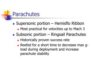
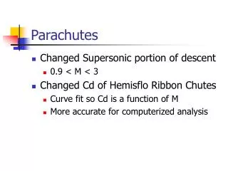
MISSION SCENARIOS AND SYSTEM CONSIDERATIONS (1) • Classification of mission scenarios • Mars missions • Thin atmosphere large parachutes, can be opened only close to the ground descent under parachute lasts no more than a few minutes • Communications during descent: DTE (X-band) or UHF (through relay SC) • Amount of information that needs to be transmitted during the EDL is small (mainly engineering telemetry) no need for high data rates • Missions to bodies with denser atmospheres (Venus, Jupiter,Titan…) • dense atmospheres smaller parachutes descent lasts much longer (up to 2 hours for Huygens) • main scientific return of the mission is achieved during the passage through the atmosphere • no or very short lifetime on the surface • all data collected during the descent (images, atmospheric properties, and engineering data) must be transmitted right away to to a relay SC overhead (DTE often not possible) • the highest the data rate, the better 6th INTERNATIONAL PLANETARY PROBE WORKSHOP – Atlanta, GA
MISSION SCENARIOS AND SYSTEM CONSIDERATIONS (2) • Main potential benefit at system level increase the volume of data transmitted during the descent phase • Need for additional antenna on the probe for phases not under main parachute no overall mass reduction • Monitoring the parachute deployment and dynamics during the descent relevant but not critical • Parachute type, size and link geometry depend very much on the mission • Huygens taken as reference mission scenario • 3 parachutes: most part of descent under stabiliser 3-m diam. chute • One-way link comms to Cassini 6th INTERNATIONAL PLANETARY PROBE WORKSHOP – Atlanta, GA
INTEGRATED PARACHUTE-ANTENNA SOLUTIONS (1) • Candidate antenna concepts • Patch array • different configurations and number of elements located on the canopy • large surface available, azimuth symmetric patterns, fixed or steerable beam • Microstrip constrained lens (feeder + lens membrane) • efficiency problems in power supply (spillover), design complexity • Dual-mode conical helix supported by suspension lines • directivity gain strongly depends on ground plane, not suitable for steerable beam • Other concepts including • Single circular patch • Horn antenna • Conical vertical array of printed antennas • Conical sleeve dipole 6th INTERNATIONAL PLANETARY PROBE WORKSHOP – Atlanta, GA
INTEGRATED PARACHUTE-ANTENNA SOLUTIONS (2) • Selected concept patch array with steerable pattern, both in elevation and azimuth • significant increase in gain • flexible design for easy adaptation to different missions, parachutes • operating frequency, number of radiating elements and inter element distance can be varied according to mission requirements • signal must be modulated and amplified on the canopy and not on the probe (avoid transmission losses) • a bidirectional link is necessary to evaluate the direction to the orbiter • Considerations on frequency band • Heritage, atmospheric attenuation, antenna sizes, etc. • S-band was selected because of smaller antenna 6th INTERNATIONAL PLANETARY PROBE WORKSHOP – Atlanta, GA
RADIATING ELEMENT DESIGN • Radiation requirements • operating frequency (S-band), bandwidth (about 40 MHz) • polarization (circular) • radiating element return loss (-10 dB) • Design optimized for robustness • ground plane + dielectric + radiating patch • dual feeding point structure (good circular polarization) • reactive splitter-fed structure to obtain two ports with a phase shift of 90° • only one radiating patch (no stacked patches) in order to simplify manufacturing Dimensions: 75 x 75 x 3 mm 6th INTERNATIONAL PLANETARY PROBE WORKSHOP – Atlanta, GA
STEERABLE PATCH ARRAY DESIGN (1) • A 12-element configuration selected • small number of elements with small reduction in radiation performance • 4 identical sub-panels: sequential rotation of step 90° is applied to antenna elements (3 by 3), to reduce the pattern of the cross polar component • phase of the excitations of the 12 elements can be varied to steer the antenna beam • system works on the basis of implicit or explicit DOA (direction of arrival) knowledge Bearing direction Phi 90° Theta 70° Bearing direction Phi 90° Theta 15° 6th INTERNATIONAL PLANETARY PROBE WORKSHOP – Atlanta, GA
STEERABLE PATCH ARRAY DESIGN (2) • Retro-directive technique • array automatically transmits in the direction of the source by re-transmitting the phase conjugate of the received signal • no need for phase shifters and no explicit DOA evaluation • Three types of retro-directive arrays • Frequency division: transmitted and received signals operating at different frequencies • Drawbacks: blocking of the receiver, difficulty to control unwanted phase shift for each radiating element • Time division: both signals at the same frequency using a time division technique • Advantage: allows for a self phase calibration of the antenna • Drawback: same frequency for transmitting & receiving signals at orbiter • Hybrid technique • Retro-directive technique compensates for deformations in the patch array • no degradation of performances for non-flat arrays 6th INTERNATIONAL PLANETARY PROBE WORKSHOP – Atlanta, GA
ANTENNA CONFIGURATIONS • 2 integrated parachute-antenna configurations • one single patch array antenna located on the top of the canopy, near the vent • not symmetric (central part of the canopy is occupied by the vent) canopy shape almost flat in region closest to the vent • Directivity very good at boresight, decreasing sharply for probe aspect angles > 70º • one antenna with three patch arrays located in the lower part of the canopy, that work in diversity mode • symmetric • angle between the normal of the antenna and the parachute axis around 45º • only one array transmits at a given time • for mission scenarios where the antenna will need to cover the full range of aspect angles 6th INTERNATIONAL PLANETARY PROBE WORKSHOP – Atlanta, GA
MATERIALS AND PROCESSES (1) • Research conducted to identify best materials for dielectric and ground plane and radiating patches • Requirements for dielectric • required permittivity constant • low density • proper range of operational temperature • flexibility • Use of textile materials for dielectric discarded due to • very high number of layers required (more than 2000 for Nylon 6-6) • difficulty to avoid air cavities during the sewing process • High-frequency circuit material RO6002 selected • Conductive fabrics also investigated for ground plane and radiating patches, but reference design based on Printed Circuit Board (PCB) • Mass budget • 12 radiating elements: 600 g • Common unit electronic devices, cabling: 400 g (conservative) 6th INTERNATIONAL PLANETARY PROBE WORKSHOP – Atlanta, GA
MATERIALS AND PROCESSES (2) • Single array substrate (easier integration) or separated dielectric pieces for each radiating element sewed to the fabrics • One pocket to cover and protect the antenna and avoid entanglement during the parachute extraction sequence • Connection between probe and antenna located on the canopy through cables for signal, control and power • Signal is transmitted in base-band to reduce RF losses • Cables routed through parachute suspension lines • Integrated parachute-antenna packing • similar process to conventional parachutes • extraction angle determined by position of antenna 6th INTERNATIONAL PLANETARY PROBE WORKSHOP – Atlanta, GA
AERODYNAMIC ANALYSIS • Disk-gap-band parachute • Antenna local load per surface unit compared to aerodynamic load on parachute determines deformations in steady-state descent • aerodynamic load depends on mission (parachute size, probe mass) and planet (gravity, density) • preferred locations for the antenna on the canopy • reinforcement tapes on the canopy reduce the concavity • Dynamic analysis to determine frequency and modes of oscillation 6th INTERNATIONAL PLANETARY PROBE WORKSHOP – Atlanta, GA
RF LINK PERFORMANCE (1) • Probe-orbiter link performance with new integrated parachute-antenna design was analyzed for a Huygens mission scenario • Atmospheric descent lasted for some 140 min • Range varied between 60000 - 70000 km • Probe aspect angle varied between 20 and 70 deg • All original link parameters (transmitter RF power, receiver, etc.) were kept constant except for the updated antenna gain 6th INTERNATIONAL PLANETARY PROBE WORKSHOP – Atlanta, GA
RF LINK PERFORMANCE (2) • Data bit rate varied to assess link performance • Original data bit rate used by Huygens was 8 Kbps • New antenna would allow for 64 Kbps increase in data volume returned • More and higher resolution images • Increase in scientific return to be traded-off with impact at system level • Mass increase • Complexity 6th INTERNATIONAL PLANETARY PROBE WORKSHOP – Atlanta, GA
PROTOTYPE AND TESTING (1) • A prototype of the integrated parachute-antenna will be implemented and tested in-flight • Objective: proof the feasibility of the concept • verify manufacturing and integration methods • test integrated parachute-antenna aerodynamic behavior • test antenna performances during a real descent • Test concept: drop the parachute from a balloon at 2 km altitude • prototype size and configuration determined by constraints imposed by test procedure (parachute size, max. payload mass, geometry, etc.) • tests not representative of real mission scenarios 6th INTERNATIONAL PLANETARY PROBE WORKSHOP – Atlanta, GA
PROTOTYPE AND TESTING (2) • 2 parachute prototypes already built and dropped from a balloon with 2 dummy antennas (same properties as planned antenna prototype) • Tests were successful conditions for antenna test (relative geometry, oscillations, etc.) as planned 6th INTERNATIONAL PLANETARY PROBE WORKSHOP – Atlanta, GA
CONCLUSIONS • Integrated parachute-antenna concept investigated • Design proposed for a retro-directive patch array (S-band) located on top of the canopy • Easily customizable as a function of the mission • Prototype being built and tested for proof of concept • Significant increase in gain wrt conventional antennas for entry probes allows for increased bit rate and scientific return • must be traded-off at system level • a bi-directional link is required with the orbiter • increased mass and complexity • Promising application to balloons • Scientific missions, high volume of data return, constantly changing link geometry • Antenna on top of balloon, similar implementation processes 6th INTERNATIONAL PLANETARY PROBE WORKSHOP – Atlanta, GA
Thank you Carlos Corral van Damme Email: cfcorral@gmv.es www.gmv.com