Download
1 / 86
860 likes | 990 Vues
1DT014/1TT821 Computer Networks I Chapter 1 Introduction. Our goal: get context, overview, “feel” of networking more depth, detail later in course approach: descriptive use Internet as example. Overview: what’s the Internet what’s a protocol? network edge network core

E N D
1DT014/1TT821Computer Networks I Chapter 1Introduction Introduction
Our goal: get context, overview, “feel” of networking more depth, detail later in course approach: descriptive use Internet as example Overview: what’s the Internet what’s a protocol? network edge network core access net, physical media Internet/ISP structure performance: loss, delay protocol layers, service models history Chapter 1: Overview of the Internet Introduction
Chapter 1: roadmap 1.1 What is the Internet? 1.2 Network edge 1.3 Network core 1.4 Network access and physical media 1.5 Internet structure and ISPs 1.6 Delay & loss in packet-switched networks 1.7 Protocol layers, service models 1.8 History Introduction
millions of connected computing devices: hosts, end-systems PCs workstations, servers PDAs phones, toasters running network apps communication links fiber, copper, radio, satellite transmission rate = bandwidth routers: forward packets (chunks of data) router workstation server mobile local ISP regional ISP company network What’s the Internet: “nuts and bolts” view Introduction
protocolscontrol sending, receiving of msgs e.g., TCP, IP, HTTP, FTP, PPP Internet: “network of networks” loosely hierarchical public Internet versus private intranet Internet standards RFC: Request for comments IETF: Internet Engineering Task Force What’s the Internet: “nuts and bolts” view router workstation server mobile local ISP regional ISP company network Introduction
Q: Why do we need a network ? What’s the Internet: a service view Introduction
communication infrastructure enables distributed applications: Web, email, games, e-commerce, database., voting, file (MP3) sharing communication services provided to apps: connectionless connection-oriented What’s the Internet: a service view Introduction
human protocols: “what’s the time?” “I have a question” introductions … specific msgs sent … specific actions taken when msgs received, or other events network protocols: machines rather than humans all communication activity in Internet governed by protocols What’s a protocol: formal def protocols define format, order of msgs sent and received among network entities, and actions taken on msg transmission, receipt Introduction
a human protocol and a computer network protocol: TCP connection response Get http://www.awl.com/kurose-ross Got the time? 2:00 <file> time What’s a protocol? Hi TCP connection req Hi Introduction
“Cool” internet appliances Internet Weather Info Web-enabled toaster+weather forecaster FordSync + Microsoft's Automotive ? WiFi Internet Picture Frame Introduction
network edge: applications and hosts network core: routers network of networks access networks, physical media: communication links A closer look at network structure: Introduction
Chapter 1: roadmap 1.1 What is the Internet? 1.2 Network edge 1.3 Network core 1.4 Network access and physical media 1.5 Internet structure and ISPs 1.6 Delay & loss in packet-switched networks 1.7 Protocol layers, service models 1.8 History Introduction
network edge: applications and hosts network core: routers network of networks access networks, physical media: communication links A closer look at network structure: Introduction
end systems (hosts): run application programs e.g. Web, email at “edge of network” client/server model client host requests, receives service from always-on server e.g. Web browser/server; FTP client/server peer-peer model: minimal (or no) use of dedicated servers e.g. Skype, BitTorrent, eMule The network edge: Introduction
Q: Which is better ? client/server model client host requests, receives service from always-on server e.g. Web browser/server; FTP client/server peer-peer model: minimal (or no) use of dedicated servers e.g. Skype, BitTorrent, eMule The network edge: Introduction
Goal: data transfer between end systems handshaking: setup (prepare for) data transfer ahead of time Hello, hello back human protocol set up “state” in two communicating hosts TCP - Transmission Control Protocol Internet’s connection-oriented service TCP service[RFC 793] reliable, in-order byte-stream data transfer loss: acknowledgements and retransmissions flow control: sender won’t overwhelm receiver congestion control: senders “slow down sending rate” when network congested Network edge: connection-oriented service Introduction
Goal: data transfer between end systems same as before! UDP - User Datagram Protocol [RFC 768]: Internet’s connectionless service unreliable data transfer no flow control no congestion control Network edge: connectionless service Introduction
Connection vs connectionless Q:why implement both TCP and UDP App’s using TCP: • HTTP (Web), FTP (file transfer), Telnet (remote login), SMTP (email) App’s using UDP: • streaming media, teleconferencing, DNS, Internet telephony Introduction
Chapter 1: roadmap 1.1 What is the Internet? 1.2 Network edge 1.3 Network core 1.4 Network access and physical media 1.5 Internet structure and ISPs 1.6 Delay & loss in packet-switched networks 1.7 Protocol layers, service models 1.8 History Introduction
mesh of interconnected routers the fundamental question: how is data transferred through net? circuit switching: dedicated circuit per call: telephone net packet-switching: data sent thru net in discrete “chunks” The Network Core Introduction
End-end resources reserved for “call” link bandwidth, switch capacity dedicated resources: no sharing circuit-like (guaranteed) performance call setup required Network Core: Circuit Switching Introduction
network resources (e.g., bandwidth) divided into “pieces” pieces allocated to calls resource piece idle if not used by owning call (no sharing) Network Core: Circuit Switching • dividing link bandwidth into “pieces” • frequency division • time division Introduction
Example: 4 users FDMA frequency time TDMA frequency time Circuit Switching: FDMA and TDMA Introduction
Numerical example • How long does it take to send a file of 640,000 bits from host A to host B over a circuit-switched network? • All links are 1.536 Mbps • Each link uses TDM with 24 slots/sec • 500 msec to establish end-to-end circuit Let’s work it out! Introduction
each end-end data stream divided into packets user A, B packets share network resources each packet uses full link bandwidth resources used as needed Bandwidth division into “pieces” Dedicated allocation Resource reservation Network Core: Packet Switching resource contention: • aggregate resource demand can exceed amount available • congestion: packets queue, wait for link use • store and forward: packets move one hop at a time • Node receives complete packet before forwarding Introduction
Sequence of A & B packets does not have fixed pattern, shared on demand statistical multiplexing. TDM: each host gets same slot in revolving TDM frame. D E Packet Switching: Statistical Multiplexing 10 Mbs Ethernet C A statistical multiplexing 1.5 Mbs B queue of packets waiting for output link Introduction
1 Mbit link each user: 100 kbps when “active” active 10% of time circuit-switching: 10 users packet switching: with 35 users, probability > 10 active less than .0004 Packet switching allows more users to use network! Packet switching versus circuit switching N users 1 Mbps link Q: how did we get value 0.0004? Introduction
Great for bursty data resource sharing simpler, no call setup Excessive congestion: packet delay and loss protocols needed for reliable data transfer, congestion control Q: How to provide circuit-like behavior? Is packet switching a “slam dunk winner?” Packet switching versus circuit switching • bandwidth guarantees needed for audio/video apps • still an unsolved problem (chapter 6) Q: human analogies of reserved resources (circuit switching) versus on-demand allocation (packet-switching)? Introduction
Packet-switched networks Circuit-switched networks FDM TDM Datagram Networks Networks with VCs Network Taxonomy Telecommunication networks • Datagram network is not either connection-oriented • or connectionless. • Internet provides both connection-oriented (TCP) and • connectionless services (UDP) to apps. Introduction
Wireless Network Wired Network Fiber Coaxial BlueTooth WLAN Network Taxonomy, cont’d Telecommunication networks • There are many other taxonomies … Introduction
Chapter 1: roadmap 1.1 What is the Internet? 1.2 Network edge 1.3 Network core 1.4 Network access and physical media 1.5 Internet structure and ISPs 1.6 Delay & loss in packet-switched networks 1.7 Protocol layers, service models 1.8 History Introduction
Q: How to connect end systems to edge router? residential access nets institutional access networks (school, company) mobile access networks Keep in mind: bandwidth (bits per second) of access network? shared or dedicated?(10M>6M ?) Access networks and physical media Introduction
Dialup via modem up to 56Kbps direct access to router (often less) Can’t surf and phone at same time: can’t be “always on” Residential access: point to point access • ADSL: asymmetric digital subscriber line • E.g. Telus • up to 1 Mbps upstream (today typically < 256 kbps) • up to 8 Mbps downstream (today typically < 1 Mbps) • FDM: 50 kHz - 1 MHz for downstream 4 kHz - 50 kHz for upstream 0 kHz - 4 kHz for ordinary telephone Introduction
HFC: hybrid fiber coax asymmetric: up to 10Mbps upstream, 1 Mbps downstream network of cable and fiber attaches homes to ISP router shared access to router among home issues: congestion, dimensioning deployment: available via cable companies Residential access: cable modems • ShawCable Introduction
Residential access: cable modems Diagram: http://www.cabledatacomnews.com/cmic/diagram.html Introduction
Cable Network Architecture: Overview Typically 500 to 5,000 homes cable headend home cable distribution network (simplified) Introduction
Cable Network Architecture: Overview cable headend home cable distribution network (simplified) Introduction
server(s) Cable Network Architecture: Overview cable headend home cable distribution network Introduction
C O N T R O L D A T A D A T A V I D E O V I D E O V I D E O V I D E O V I D E O V I D E O 5 6 7 8 9 1 2 3 4 Channels Cable Network Architecture: Overview FDM: cable headend home cable distribution network Introduction
company/univ local area network (LAN) connects end system to edge router Ethernet: shared or dedicated link connects end system and router 10 Mbs, 100Mbps, Gigabit Ethernet deployment: institutions, home LANs happening now LANs: chapter 5 Company access: local area networks Introduction
shared wireless access network connects end system to router via base station aka “access point” wireless LANs: 802.11b (WiFi): 11 Mbps wider-area wireless access provided by telco operator 3G WAP/GPRS in Europe/North America router base station mobile hosts Wireless access networks Introduction
Typical home network components: ADSL or cable modem router/firewall/NAT Ethernet wireless access point Home networks wireless laptops to/from cable headend cable modem router/ firewall wireless access point Ethernet (switched) Introduction
Bit: propagates betweentransmitter/rcvr pairs physical link: what lies between transmitter & receiver guided media: signals propagate in solid media: copper, fiber, coax unguided media: signals propagate freely, e.g., radio Problem ? Twisted Pair (TP) two insulated copper wires Category 3: traditional phone wires, 10 Mbps Ethernet Category 5 TP: 100Mbps Ethernet Physical Media Introduction
Coaxial cable: two concentric copper conductors bidirectional baseband: single channel on cable legacy Ethernet broadband: multiple channel on cable HFC Physical Media: coax Introduction
Physical Media: coax, fiber Fiber optic cable: • glass fiber carrying light pulses, each pulse a bit • high-speed operation: • high-speed point-to-point transmission (e.g., 5 Gps) • low error rate: repeaters spaced far apart ; immune to electromagnetic noise Introduction
signal carried in electromagnetic spectrum no physical “wire” bidirectional propagation environment effects: reflection obstruction by objects interference Physical media: radio Radio link types: • terrestrial microwave • e.g. up to 45 Mbps channels • LAN (e.g., WaveLAN) • 2Mbps, 11Mbps • wide-area (e.g., cellular) • e.g. 3G: hundreds of kbps • satellite • up to 50Mbps channel (or multiple smaller channels) • 270 msec end-end delay • geosynchronous versus LEOS Introduction
Chapter 1: roadmap 1.1 What is the Internet? 1.2 Network edge 1.3 Network core 1.4 Network access and physical media 1.5 Internet structure and ISPs 1.6 Delay & loss in packet-switched networks 1.7 Protocol layers, service models 1.8 History Introduction
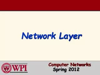
roughly hierarchical at center: “tier-1” ISPs (e.g., UUNet, BBN/Genuity, Sprint, AT&T), national/international coverage treat each other as equals NAP Tier-1 providers also interconnect at public network access points (NAPs) Tier-1 providers interconnect (peer) privately Internet structure: network of networks Tier 1 ISP Tier 1 ISP Tier 1 ISP Introduction
“Tier-2” ISPs: smaller (often regional) ISPs Connect to one or more tier-1 ISPs, possibly other tier-2 ISPs NAP Tier-2 ISPs also peer privately with each other, interconnect at NAP • Tier-2 ISP pays tier-1 ISP for connectivity to rest of Internet • tier-2 ISP is customer of tier-1 provider Tier-2 ISP Tier-2 ISP Tier-2 ISP Tier-2 ISP Tier-2 ISP Internet structure: network of networks Tier 1 ISP Tier 1 ISP Tier 1 ISP Introduction
“Tier-3” ISPs and local ISPs last hop (“access”) network (closest to end systems) Tier 3 ISP local ISP local ISP local ISP local ISP local ISP local ISP local ISP local ISP NAP Local and tier- 3 ISPs are customers of higher tier ISPs connecting them to rest of Internet Tier-2 ISP Tier-2 ISP Tier-2 ISP Tier-2 ISP Tier-2 ISP Internet structure: network of networks Tier 1 ISP Tier 1 ISP Tier 1 ISP Introduction