Download
1 / 47
1.32k likes | 2.21k Vues
Principles of ADCP Operation. (How these things work). ADCPs Measure Water Velocity with SOUND. Sounds are simply pressure waves that travel through gasses, liquids, or solids Sound waves have crests and troughs that correspond to bands of high and low pressure

E N D
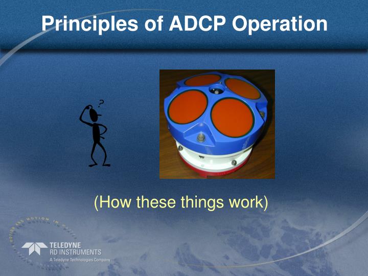
Principles of ADCP Operation (How these things work)
ADCPs Measure Water Velocity with SOUND • Sounds are simply pressure waves that travel through gasses, liquids, or solids • Sound waves have crests and troughs that correspond to bands of high and low pressure • We perceive sounds by these pressure waves vibrating our eardrums, which with the inner ear convert the mechanical energy of pressure waves to electrical signals interpreted by our brains • Humans can hear sounds in the range 40-24,000 Hz • Common ADCP range is 300,000-3,000,0000 Hz
Sound/Wave Terminology Waves – Water wave crests and troughs are high and low water elevations. Sound wave “crests” and “troughs” consist of bands of high and low air or water pressure. + Crest Trough -
Sound/Wave Terminology Wavelength (l) – The distance between successive wave crests. (units: meters) + Wavelength - Wavelength = 1 m
Sound/Wave Terminology Frequency (f) – The number of wave crests that pass an observation point per unit time. (units: Hertz [Hz] which means “per second”) + Movement of Waves Crest Crest Crest Crest Crest Observation Point - 1 Second Frequency= 4 Hz
Sound/Wave Terminology Speed of sound (C) – The speed at which waves propagate, or move (units: m/s) C = f x l Frequency (f) = 4 Hz, Wavelength (l) = 1 m + Movement of Waves Crest Crest Crest Crest Crest Observation Point - 1 Second Speed of sound = 4 Hz x 1 m = 4 m/s (more realistic ADCP example, 300,000 Hz × 5 mm = 1500 m/s )
Doppler Principle In General- the change in frequency from a sound (or light) source to an observer is proportional to the speed at which the distance between the source and observer is increasing or decreasing Applied to ADCPs- The change in frequency of a sound wave transmitted from a transducer and reflected back off particles in the water, is proportional to the speed at which the distance between the transducer and particles is increasing or decreasing
Doppler Video doppler video\doppler.mov
Doppler Terminology Relative Velocity (V) – relative velocity between the sound source and the sound wave receiver (the speed at which the receiver is moving toward the sound source; units: m/s) Receiver 12 m/s 7 m/s Source V= 5 m/s
Doppler Terminology Source Frequency (Fs ) – the transmitted frequency of waves from a sound source (units: Hz) Examples: Fs= 300 - 1,000 Hz Trumpet Fs= 300,000 – 5,000,000 Hz ADCP Transducer
Doppler Terminology Doppler Shift (FD ) – the change in frequency from a sound source to an observer due to the distance between the source and observer increasing or decreasing
Doppler Principle FD = FS * V/C FD = Doppler Shift Frequency (change in frequency) FS = Source Frequency V = Relative velocity between source and receiver C = Speed of Sound
Sound Sources/Observers Only a small portion of the transmitted sound returns to the receivers
Corrected Doppler Shift Equation FD = 2FS * V/C
Doppler Shift Measures Radial Velocityfor waves of fequency of 8 Hz Observer speed Apparent speed 0 waves / unit time 8 waves / unit time 4 waves / unit time 12 waves / unit time 4 waves / unit time 60 10 waves / unit time
Opposing Beams Horizontal Velocity Velocity with a vertical component East-West Pair North-South Pair Water velocity vector Measured component Unmeasured component
TRDI’s 4-Transducer “Janus” Configuration Measures x, y, z and error velocities
Homogenous Flow Assumption Homogeneous (Low error velocity) Non-homogeneous (High error velocity)
Why is Error Velocity Important? • With error velocity you can tell if something is ‘odd’ • Inhomogeneous flow • Fish • Stationary objects in the water – limbs, old bridge pilings • With the software you can reject the data with high error velocity – better and more reliable data (more about this later)
BroadBand vs NarrowBand • So far everything has been the same for BroadBand or NarrowBand ADCPs • How is BroadBand different from NarrowBand? • How does this affect my data?
Coded Transmit Waveform Monochromatic Transmit Waveform = NarrowBand Coded Transmit Waveform = BroadBand Code Element
So What? • BroadBand has noise that is 50 times lower than Narrowband – more information into the water means better data back from the water. Like taking pictures with an 8 megapixel camera compared to an old 320x240 pixel webcam.
It is easy to see the difference BroadBand NarrowBand
And in the Water? • More of the water is measured. Small cells let you measure closer to the surface, closer to the bottom and closer to the edges. • The data in the measured cells has lower noise so the discharge is more accurate • The noise of bottom tracking is also much lower
BroadBand allows profiling modes: each for a specific application • Mode 1- general purpose • Mode 5 – slow and shallow water • Mode 11 – slow and very shallow water • Mode 12 – fast and shallow water (optional upgrade)
Decisions, DecisionsWhich Mode to Use? • Let the setup wizard decide! • Tell the wizard how deep and how fast • The wizard will set the mode for you • With experience and advanced training, you can fine-tune the modes
Bottom Tracking • Bed velocity or bottom-tracking measurements are similar to the water-velocity measurements • Bottom-tracking pulses are sent separate from the water measurement pulses • Bottom-tracking pulses are longer than water pulses • Also measures water depths for discharge computations
Bottom Tracking 2 Long Pulse Short Pulse Entire beam does not illuminate the bottom at one time Entire beam does illuminate the bottom at one time
Bottom Tracking Short pulse width Long backscattered pulse width suspended sediment Near-bed sediment Long Pulse Bed Short pulse Small area illuminated Large area illuminated
Summary of ADCP Operation • Water velocity measurement • Boat velocity measurement • Interaction of ADCP with WinRiver
Water velocity measurement • Measurements made relative to ADCP • Velocity measured from reflections from particles in the water column • Includes both water and boat velocity • Pulses are short and coded • BroadBand is 50 times less noisy than NarrowBand
Boat velocity measurement • Reference velocity for water measurements • Bottom tracking • Velocity measured from reflections from streambed • Pulses are typically quite long so that the entire bottom is ensonified at once • DGPS can be used but is less accurate
ADCP with WinRiver • WinRiver is the user interface to the ADCP • ADCP measures water and boat velocity • WinRiver) • communicates with ADCP (ADP) • displays ADCP (ADP) measurement results • computes discharge • allows adjustment of parameters • Correct setup of the instruments are crucial to collecting good data
Advanced Topics • Dual Pulse processing • Range gating • Side lobes • Coordinate systems
Pulse Pairs - Phase Shift – Time Dilation • 2 sound waves (pulses) sent with a set time lag between them • Effect of frequency measured by either phase shift or time dilation or both
Phase Shift and Time Dilation 0 40 B A 400 A B
One Ping - Two Samples F d = dT T = Lag L Pulse Length Change in Phase DEPTH Time Interval TIME
ADCPs Measure Velocity Profiles Depth Cell Mechanical current meter ADCP
Range Gating an Acoustic Pulse Bin 4 cell 4 Bin 3 cell 3 Range From ADCP Bin 2 cell 2 cell 1 Bin 1 Blank echo echo echo echo start end Gate 4 Gate 3 Gate 1 Gate 2 Transmit pulse Time
Bin Mapping / Pitch and Roll Depth Cell Depth Cell mapping Pitch or Roll angle
Coordinate Systems X 3 Y Y 1 2 4 X Beam [EX00nnn] Radial velocities. No transformations. Instrument [EX01nnn] Beam transformation matrix used, but no pitch/roll or heading. Velocities rotated to X-Y-Z coordinates. X = Beams 3 & 4. Y = Beams 1 & 2. Z = Vertical component Ship – (Recommended) [EX10nnn]Beam transformation used. Pitch/roll applied, but no heading. Velocities rotated to X-Y-Z coordinates. Earth [EX11nnn] Same as Ship, but heading applied. Velocities rotated to E-W, N-S, Up (ENU).
Side Lobe Characteristics Transducer 2 Transducer 1
Side Lobes and Profiling Range Water Depth (D) D * cos() =