Download
1 / 12
120 likes | 265 Vues
JTAG on CAN with LMB. Estimation of time for JTAG/CAN conversion and propagation using the ATLAS/DCS LMB. Present CAN Bus system. 2 PCs, Win98 and Linux 3 CAN nodes Node with PCI I/F Node with VME I/F Local Monitor Box

E N D
JTAG on CAN with LMB Estimation of time for JTAG/CAN conversion and propagation using the ATLAS/DCS LMB C.Fukunaga/TGC electronics meeting at CERN Feb.,11,2000
Present CAN Bus system • 2 PCs, Win98 and Linux • 3 CAN nodes • Node with PCI I/F • Node with VME I/F • Local Monitor Box • Operation of LMB from both side confirmed with DCS stndrd AVR software • Our ultimate goal is to control the TTC with JTAG via CAN, but presently no TTC connection has been achieved. C.Fukunaga/TGC electronics meeting at CERN Feb.,11,2000
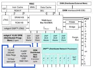
Structure of LMB • Two mprocessors of ATMEL • AVR AT90S2313-10 10MHz,1Kbytes • AVR AT90S1200-12 12MHz • CAN Bus driver and controller C.Fukunaga/TGC electronics meeting at CERN Feb.,11,2000
How to make JTAG with LMB • With CS = 0, Serial I/F of Can controller is used to input/output CAN data. • With CS = 1, SCLK,SDI,SDO with CSADC of PortD are used for JTAG lines. C.Fukunaga/TGC electronics meeting at CERN Feb.,11,2000
CAN JTAG conversion 1 • Put desired TMS,TDI sequence of JTAG into a CAN packet • In a packet total 32 steps of both TMS and TDI are stored. C.Fukunaga/TGC electronics meeting at CERN Feb.,11,2000
CAN JTAG conversion 2 • Results (see another slide for execution) • Program size 226 bytes • Data size 12 bytes • 5041 Cycle counts • 504.1msec/32 TMS instruction(=1 CAN packet) • LMB mproc. takes 15.8msec. for 1000 TMS instructions. C.Fukunaga/TGC electronics meeting at CERN Feb.,11,2000
CAN Bus network 1 • For JTAG 32TMS operation, we need two packets(Tx and Rx) and an extra packet for end flag. • The time consumption will be increased lineary with number of TMS operations. • The time consumption of the network access is serious than CAN/JTAG conversion proc. C.Fukunaga/TGC electronics meeting at CERN Feb.,11,2000
CAN Bus network 2 • Transfer Speed over the simplest CAN bus (1 to 1) with the TMS bit length (CAN bus 125Kbaud) • Rate=16.36KTMS/s C.Fukunaga/TGC electronics meeting at CERN Feb.,11,2000
Transfer Rate versus Various CAN baud setting: For large scale CAN bus, baud rate 125K is recommended CAN Bus network 3 C.Fukunaga/TGC electronics meeting at CERN Feb.,11,2000
(Rough) Estimation for Total system • Assume total 500TMS/patch panel, and CAN baudrate 125Kbit/s. • It takes at least 31ms for one patch panel. • Since CAN is in principle 1 to 1 connection, we must multiply 12 for duration of 1 PS pack --> 372ms(0.37s) • Thus if we have 100 PS pack, it will take 37s for JTAG initialization. C.Fukunaga/TGC electronics meeting at CERN Feb.,11,2000