Download
1 / 3
30 likes | 124 Vues
Deki Electronics is one of the largest Metallised Film Capacitor Manufacturers in India. We are manufacturing & supplying the best Metallised Polyester Film Capacitors in India at the very competitive price.

E N D
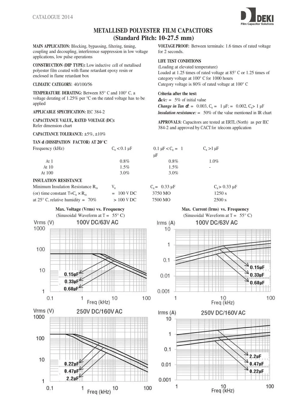
CATALOGUE2014 METALLISEDPOLYESTERFILMCAPACITORS (StandardPitch:10-27.5mm) VOLTAGE PROOF: Between terminals: 1.6 times of rated voltage for 2 seconds. MAIN APPLICATION: Blocking, bypassing, filtering, timing, coupling and decoupling, interference suppression in low voltage applications, low pulse operations LIFE TEST CONDITIONS (Loading at elevated temperature) Loaded at 1.25 times of rated voltage at 85° C or 1.25 times of category voltage at 100° C for 1000 hours Category voltage is 80% of rated voltage at 100° C CONSTRUCTION (DIP TYPE): Low inductive cell of metallised polyester film coated with flame retardant epoxy resin or enclosed in flame retardant box CLIMATIC CATEGORY: 40/100/56 TEMPERATURE DERATING: Between 85° C and 100° C, a voltage derating of 1.25% per °C on the rated voltage has to be applied Criteria after the test: c/c: = 5% of initial value Change in Tan d: = Insulation resistance: = 0.003, CR = 50% of the value mentioned in IR chart 1 µF; = 0.002, CR> 1 µF APPLICABLE SPECIFICATION: IEC 384-2 CAPACITANCE VALUE, RATED VOLTAGE (DC): Refer dimension chart APPROVALS: Capacitors are tested at ERTL (North) as per IEC 384-2 and approved by CACT for telecom application CAPACITANCE TOLERANCE: ±5%, ±10% TANd Frequency(kHz) CR < 0.1 µF (DISSIPATION FACTOR) AT 20°C 0.1 µF< CR = µF CR >1µF 1 At10.8% 0.8% 1.0% At10 1.5% 1.5% - At100 3.0% 3.0% INSULATIONRESISTANCE MinimumInsulationResistance RIS VR (or) timeconstant=CR × RIS = 100 V DC 3750 MO1250 s at 25° C,relativehumidity= 70%> 100 V DC 7500 MO2500 s CR = 0.33 µF CR > 0.33 µF Max.Voltage (Vrms)vs.Frequency Max.Current(Irms)vs.Frequency (Sinusoidal Waveformat T = 55° C) (Sinusoidal Waveformat T = 55° C)
CATALOGUE2014 NOTE:Thederatingcurves are basedon the actualobservedvalues.
CATALOGUE2014 METALLISEDPOLYESTERFILMCAPACITORS(StandardPitch:10-27.5mm) Orderingcodes andpackagingunits- DipType Rated Voltage Rated Cap.(µF) Dimensions(mm) L d ±0.5 ±0.05 13 0.6 W H S F DV/DT V/µs 28 Wt. g 0.60 Ordering code 02104+2A*^ Packingunits Ammo Bulk 1500 1000 ±0.5 5.0 ±0.5 10.0 ±0.5 10.0 ±0.5 10.0 100VDC 0.150 6.0 12.0 13 0.6 10.0 10.0 28 0.65 02 154 +2A*^1500 1000 0.220 7.0 12.0 13 0.6 10.0 10.0 28 0.90 02224+2A*^ 1500 1000 0.330 6.0 12.0 19 0.8 10.0 10.0 20 0.90 02 334 +2A*^- 1000 0.470 9.0 15.0 19 0.8 15.0 15.0 20 0.90 02474+2A*^ -1000 0.680 6.0 12.0 19 0.8 15.0 15.0 20 1.00 02 684 +2A*^- 1000 1.000 9.0 15.0 19 0.8 15.0 15.0 20 1.30 02105+2A*^ -1000 1.500 6.0 15.0 27 0.8 22.5 15.0 8 2.00 02 155 +2A*^- 1000 2.200 10.0 18.0 27 0.8 22.5 15.0 8 2.80 02225+2A*^ -500 3.300 8.5 18.0 27 0.8 22.5 22.5 8 4.00 02 335 +2A*^- 500 4.700 15.0 22.0 27 0.8 22.5 -7 5.20 02475+2A*^ -500 250VDC 0.027 4.0 9.0 13 0.6 10.0 10.0 70 0.65 02 273 +2E*^1500 1000 0.033 4.0 9.0 13 0.6 10.0 10.0 70 0.65 02333+2E*^ 1500 1000 0.047 6.0 10.0 13 0.6 10.0 10.0 70 0.70 02 473 +2E*^1500 1000 0.068 7.0 12.0 13 0.610.0 10.0 70 0.70 02683+2E*^ 1500 1000 0.082 5.0 10.0 13 0.6 10.0 10.0 70 0.75 02 823 +2E*^1500 1000 0.100 6.0 12.0 13 0.6 10.0 10.0 70 0.75 02104+2E*^ 1500 1000 0.150 6.0 12.0 13 0.8 10.0 10.0 70 0.80 02 154 +2E*^- 1000 0.220 6.0 12.0 19 0.8 15.0 15.0 28 1.40 02224+2E*^ -1000 0.330 7.0 13.0 19 0.8 15.0 15.0 28 1.40 02 334 +2E*^- 1000 0.470 9.015.0 19 0.8 15.0 15.0 28 2.10 02474+2E*^ -1000 0.680 9.0 14.0 19 0.8 15.0 15.0 28 2.90 02 684 +2E*^- 1000 1.000 7.5 16.5 27 0.8 22.5 22.5 12 3.60 02105+2E*^ -500 1.500 8.5 17.5 27 0.8 22.5 - 12 5.10 02 155 +2E*^- 500 2.200 10.0 20.0 27 0.8 22.5 -12 6.50 02225+2E*^ -250 3.300 12.0 21.0 27 0.8 22.5 12 7.50 02 335 +2E*^- 250 400VDC 0.010 4.0 9.0 13 0.6 10.0 10.0 110 0.60 02103+2G*^ 1500 1000 0.015 6.0 15.0 13 0.6 10.0 10.0 110 0.60 02 153 +2G*^1500 1000 0.022 6.0 12.0 13 0.610.0 10.0 110 0.60 02223+2G*^ 1500 1000 0.033 5.0 10.0 13 0.6 10.0 10.0 110 0.60 02 333 +2G*^1500 1000 0.047 6.0 12.0 13 0.8 10.0 10.0 110 0.62 02473+2G*^ -1000 0.068 6.0 12.0 13 0.8 10.0 10.0 110 0.70 02 683 +2G*^- 1000 0.100 6.0 12.5 19 0.8 15.0 15.0 44 1.00 02104+2G*^ -1000 0.150 8.0 16.0 19 0.8 15.0 15.0 44 1.30 02 154 +2G*^- 1000 0.2208.0 15.0 19 0.8 15.0 15.0 44 1.70 02224+2G*^ -1000 0.330 6.0 15.0 27 0.8 22.5 22.5 20 2.60 02 334 +2G*^- 1000 0.470 7.5 16.5 27 0.8 22.5 22.5 20 3.40 02474+2G*^ -500 0.680 8.0 15.0 27 0.8 22.5 - 20 3.50 02 564 +2G*^- 500 0.820 7.0 16.0 320.8 27.5 -16 4.00 02824+2G*^ -500 1.000 7.0 16.0 32 0.8 27.5 - 16 4.00 02 105 +2G*^- 250 1.500 10.0 18.0 32 0.8 27.5 -16 5.00 02155+2G*^ -250 2.200 10.3 19.6 31 0.8 27.5 - 16 6.87 02 225 +2G*^- 250 3.300 13.7 21.2 31 0.8 27.5 -16 9.50 02335+2G*^ -250 630VDC 0.011 5.0 12.0 13 0.6 10.0 10.0 70 0.65 02 103 +2J*^1500 1000 0.015 6.0 12.0 13 0.6 10.0 10.0 70 0.65 02153+2J*^ 1500 1000 0.022 6.0 12.0 13 0.6 10.0 10.0 70 0.70 02 223 +2J*^1500 1000 0.033 6.0 12.0 19 0.8 15.0 15.0 70 1.00 02333+2J*^ -1000 0.047 7.0 13.0 19 0.8 15.0 15.0 70 1.20 02 473 +2J*^- 1000 0.0688.0 14.0 19 0.8 15.0 15.0 70 1.40 02683+2J*^ -1000 0.082 8.0 14.5 19 0.8 15.0 15.0 70 1.80 02 823 +2J*^- 1000 0.110 8.0 16.0 19 0.8 15.0 15.0 70 2.00 02104+2J*^ -1000 0.150 8.0 16.0 19 0.8 15.0 15.0 70 2.50 02 154 +2J*^- 500 0.220 8.0 15.0 27 0.8 22.5 22.5 28 3.00 02224+2J*^ -500 0.330 10.0 19.0 32 0.8 27.5 - 24 5.00 02 334 +2J*^- 250 0.470 12.0 21.0 32 0.8 27.5 -24 6.50 02474+2J*^ -250 1.000 17.0 29.0 31 0.8 27.5 24 9.50 02 105 +2J*^- 250 1000VDC 0.180 10.0 22.5 31 0.8 27.5 -02184 + 3A*^ -250 0.470 16.0 28.0 31 0.8 27.5 -02 474 + 3A*^ -250 0.100 W L H lmin17mm d S 35