Download
1 / 201
2.28k likes | 2.75k Vues
Introduction to Microstrip Antennas. David R. Jackson Dept. of ECE University of Houston. Contact Information. David R. Jackson Dept. of ECE N308 Engineering Building 1 University of Houston Houston, TX 77204-4005 Phone: 713-743-4426 Fax: 713-743-4444 Email: djackson@uh.edu.

E N D
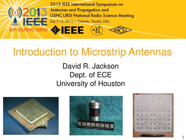
Introduction to Microstrip Antennas David R. Jackson Dept. of ECE University of Houston
Contact Information David R. Jackson Dept. of ECE N308 Engineering Building 1 University of Houston Houston, TX 77204-4005 Phone: 713-743-4426 Fax: 713-743-4444 Email: djackson@uh.edu
Purpose of Short Course • Provide an introduction to microstrip antennas. • Provide a physical and mathematical basis for understanding how microstrip antennas work. • Provide a physical understanding of the basic physical properties of microstrip antennas. • Provide an overview of some of the recent advances and trends in the area (but not an exhaustive survey – directed towards understanding the fundamental principles).
Additional Resources • Some basic references are provided at the end of these viewgraphs. • You are welcome to visit a website that goes along with a course at the University of Houston on microstrip antennas (PowerPoint viewgraphs from the course may be found there, along with the viewgraphs from this short course). ECE 6345: Microstrip Antennas http://www.egr.uh.edu/courses/ece/ece6345/web/welcome.html Note: You are welcome to use anything that you find on this website, as long as you please acknowledge the source.
Outline • Overview of microstrip antennas • Feeding methods • Basic principles of operation • General characteristics • CAD Formulas • Radiation pattern • Input Impedance • Circular polarization • Circular patch • Improving bandwidth • Miniaturization • Reducing surface waves and lateral radiation
Outline • Overview of microstrip antennas • Feeding methods • Basic principles of operation • General characteristics • CAD Formulas • Radiation pattern • Input Impedance • Circular polarization • Circular patch • Improving bandwidth • Miniaturization • Reducing surface waves and lateral radiation
Overview of Microstrip Antennas Also called “patch antennas” • One of the most useful antennas at microwave frequencies (f> 1 GHz). • It usually consists of a metal “patch” on top of a grounded dielectric substrate. • The patch may be in a variety of shapes, but rectangular and circular are the most common. Coax feed Microstrip line feed
Overview of Microstrip Antennas Common Shapes Rectangular Square Circular Annular ring Elliptical Triangular
Overview of Microstrip Antennas History • Invented by Bob Munson in 1972 (but earlier work by Dechamps goes back to1953). • Became popular starting in the 1970s. G. Deschamps and W. Sichak, “Microstrip Microwave Antennas,” Proc. of Third Symp. on USAF Antenna Research and Development Program, October 18–22, 1953. R. E. Munson, “Microstrip Phased Array Antennas,” Proc. of Twenty-Second Symp. on USAF Antenna Research and Development Program, October 1972. R. E. Munson, “Conformal Microstrip Antennas and Microstrip Phased Arrays,” IEEE Trans. Antennas Propagat., vol. AP-22, no. 1 (January 1974): 74–78.
Overview of Microstrip Antennas Advantages of Microstrip Antennas • Low profile (can even be “conformal,” i.e. flexible to conform to a surface). • Easy to fabricate (use etching and photolithography). • Easy to feed (coaxial cable, microstrip line, etc.). • Easy to use in an array or incorporate with other microstrip circuit elements. • Patterns are somewhat hemispherical, with a moderate directivity (about 6-8dB is typical).
Overview of Microstrip Antennas Disadvantages of Microstrip Antennas • Low bandwidth (but can be improved by a variety of techniques). Bandwidths of a few percent are typical. Bandwidth is roughly proportional to the substrate thickness and inversely proportional to the substrate permittivity. • Efficiency may be lower than with other antennas. Efficiency is limited by conductor and dielectric losses*, and by surface-wave loss**. • Only used at microwave frequencies and above (the substrate becomes too large at lower frequencies). • Cannot handle extremely large amounts of power (dielectric breakdown). * Conductor and dielectric losses become more severe for thinner substrates. ** Surface-wave losses become more severe for thicker substrates (unless air or foam is used).
Overview of Microstrip Antennas Applications Applications include: • Satellite communications • Microwave communications • Cell phone antennas • GPS antennas
Overview of Microstrip Antennas Microstrip antenna Filter DC supply Micro-D connector K-connector LNA PD Fiber input with collimating lens Diplexer Microstrip Antenna Integrated into a System: HIC Antenna Base-Station for 28-43 GHz (Photo courtesy of Dr. Rodney B. Waterhouse)
Overview of Microstrip Antennas Arrays Linear array (1-D corporate feed) 22 array 2-D 8X8 corporate-fed array 4 8 corporate-fed / series-fed array
Overview of Microstrip Antennas Wraparound Array (conformal) The substrate is so thin that it can be bent to “conform” to the surface. (Photo courtesy of Dr. Rodney B. Waterhouse)
Overview of Microstrip Antennas y W x L h Rectangular patch r Note: L is the resonant dimension. The width W is usually chosen to be larger than L (to get higher bandwidth). However, usually W<2L (to avoid problems with the (0,2) mode). W=1.5L is typical.
Overview of Microstrip Antennas y a x r h Circular Patch The location of the feed determines the direction of current flow and hence the polarization of the radiated field.
Outline • Overview of microstrip antennas • Feeding methods • Basic principles of operation • General characteristics • CAD Formulas • Radiation pattern • Input Impedance • Circular polarization • Circular patch • Improving bandwidth • Miniaturization • Reducing surface waves and lateral radiation
Feeding Methods Some of the more common methods for feeding microstrip antennas are shown. The feeding methods are illustrated for a rectangular patch, but the principles apply for circular and other shapes as well.
Feeding Methods Coaxial Feed y z Surface current A feed along the centerline is the most common (minimizes higher-order modes and cross-pol). W x x Feed at (x0, y0) L
Feeding Methods Coaxial Feed (The resistance varies as the square of the modal field shape.) • Advantages: • Simple • Directly compatible with coaxial cables • Easy to obtain input match by adjusting feed position z y • Disadvantages: • Significant probe (feed) radiation for thicker substrates • Significant probe inductance for thicker substrates • Not easily compatible with arrays x W x L
Feeding Methods Inset Feed • Advantages: • Simple • Allows for planar feeding • Easy to use with arrays • Easy to obtain input match Microstrip line • Disadvantages: • Significant line radiation for thicker substrates • For deep notches, patch current and radiation pattern may show distortion
Feeding Methods Inset Feed Recent work has shown that the resonant input resistance varies as x0 Wf S W L The coefficients A and B depend on the notch width S but (to a good approximation) not on the line width Wf. Y. Hu, D. R. Jackson, J. T. Williams, and S. A. Long, “Characterization of the Input Impedance of the Inset-Fed Rectangular Microstrip Antenna,” IEEE Trans. Antennas and Propagation, Vol. 56, No. 10, pp. 3314-3318, Oct. 2008.
Feeding Methods Patch Microstrip line Proximity-coupled Feed (Electromagnetically-coupled Feed) • Advantages: • Allows for planar feeding • Less line radiation compared to microstrip feed • Disadvantages: • Requires multilayer fabrication • Alignment is important for input match
Feeding Methods Patch Microstrip line Gap-coupled Feed • Advantages: • Allows for planar feeding • Can allow for a match even with high edge impedances, where a notch might be too large (e.g., when using high permittivity) Gap • Disadvantages: • Requires accurate gap fabrication • Requires full-wave design
Feeding Methods Aperture-coupled Patch (ACP) • Advantages: • Allows for planar feeding • Feed-line radiation is isolated from patch radiation • Higher bandwidth is possible since probe inductance is eliminated (allowing for a thick substrate), and also a double-resonance can be created • Allows for use of different substrates to optimize antenna and feed-circuit performance Patch Slot • Disadvantages: • Requires multilayer fabrication • Alignment is important for input match Microstrip line
Outline • Overview of microstrip antennas • Feeding methods • Basic principles of operation • General characteristics • CAD Formulas • Radiation pattern • Input Impedance • Circular polarization • Circular patch • Improving bandwidth • Miniaturization • Reducing surface waves and lateral radiation
Basic Principles of Operation • The basic principles are illustrated here for a rectangular patch, but the principles apply similarly for other patch shapes. • We use the cavity model to explain the operation of the patch antenna. z h PMC Y. T. Lo, D. Solomon, and W. F. Richards, “Theory and Experiment on Microstrip Antennas,” IEEE Trans. Antennas Propagat., vol. AP-27, no. 3 (March 1979): 137–145.
Basic Principles of Operation Main Ideas: • The patch acts approximately as a resonant cavity(with short-circuit (PEC) walls on top and bottom, open-circuit (PMC) walls on the edges). • In a cavity, only certain modes are allowed to exist, at different resonance frequencies. • If the antenna is excited at a resonance frequency, a strong field is set up inside the cavity, and a strong current on the (bottom) surface of the patch. This produces significant radiation (a good antenna). Note: As the substrate thickness gets smaller the patch current radiates less, due to image cancellation. However, the Q of the resonant mode also increases, making the patch currents stronger at resonance. These two effects cancel, allowing the patch to radiate well even for small substrate thicknesses.
Basic Principles of Operation A microstrip antenna can radiate well, even with a thin substrate. • As the substrate gets thinner the patch current radiates less, due to image cancellation (current and image are separated by 2h). • However, the Q of the resonant cavity mode also increases, making the patch currents stronger at resonance. • These two effects cancel, allowing the patch to radiate well even for thin substrates. z x
Basic Principles of Operation Thin Substrate Approximation On patch and ground plane: Inside the patch cavity, because of the thin substrate, the electric field vector is approximately independent of z. Hence z h
Basic Principles of Operation Thin Substrate Approximation Magnetic field inside patch cavity:
Basic Principles of Operation Thin Substrate Approximation Note: The magnetic field is purely horizontal. (The mode is TMz.) z h
Basic Principles of Operation y L W x h Magnetic-wall Approximation On the edges of the patch: (Js is the sum of the top and bottom surface currents.) On the bottom surface of the patch conductor, at the edge of the patch, we have Also,
Basic Principles of Operation y L W x h Magnetic-wall Approximation Since the magnetic field is approximately independent of z, we have an approximate PMC condition on the entire vertical edge. or PMC h PMC Model Actual patch
Basic Principles of Operation y L W x Magnetic-wall Approximation Hence, h (Neumann B.C.) PMC
Basic Principles of Operation y W x L Resonance Frequencies From separation of variables: PMC (TMmn mode) We then have Hence
Basic Principles of Operation y W x L Resonance Frequencies We thus have PMC Recall that Hence
Basic Principles of Operation y W x L Resonance Frequencies Hence PMC (resonance frequency of (m,n) mode)
Basic Principles of Operation y Current W x L Dominant (1,0) mode This is the mode with the lowest resonance frequency. This mode is usually used because the radiation pattern has a broadside beam. This mode acts as a wide dipole (width W) that has a resonant length of 0.5 guided wavelengths in the x direction.
Basic Principles of Operation Resonance Frequency of Dominant Mode The resonance frequency is mainly controlled by the patch length Land the substrate permittivity. Approximately, (assuming PMC walls) This is equivalent to saying that the length L is one-half of a wavelength in the dielectric. (1,0) mode: Note: A higher substrate permittivity allows for a smaller antenna (miniaturization) – but with a lower bandwidth.
Basic Principles of Operation y L L L x Le Resonance Frequency of Dominant Mode The resonance frequency calculation can be improved by adding a “fringing length extension” L to each edge of the patch to get an “effective length” Le. Note: Some authors use effective permittivity in this equation. This would change the formula for Le.
Basic Principles of Operation Resonance Frequency of Dominant Mode Hammerstad formula: Note: Even though the Hammerstad formula involves an effective permittivity, we still use the actual substrate permittivity in the resonance frequency formula.
Basic Principles of Operation Resonance Frequency of Dominant Mode Note: This is a good “rule of thumb” to give a quick estimate.
Basic Principles of Operation Results: Resonance Frequency The resonance frequency has been normalized by the zero-order value (without fringing): r = 2.2 W/ L = 1.5 fN = f / f0
Outline • Overview of microstrip antennas • Feeding methods • Basic principles of operation • General characteristics • CAD Formulas • Radiation pattern • Input Impedance • Circular polarization • Circular patch • Improving bandwidth • Miniaturization • Reducing surface waves and lateral radiation
General Characteristics Bandwidth • The bandwidth is directly proportional to substrate thickness h. • However, if h is greater than about 0.050, the probe inductance (for a coaxial feed) becomes large enough so that matching is difficult. • The bandwidth is inversely proportional to r (a foam substrate gives a high bandwidth). • The bandwidth of a rectangular patch is proportional to the patch width W (but we need to keep W < 2L ; see the next slide).
General Characteristics Width Restriction for a Rectangular Patch fc f02 f01 f10 W=1.5L is typical.
General Characteristics Some Bandwidth Observations • For a typical substrate thickness (h /0= 0.02), and a typical substrate permittivity (r = 2.2) the bandwidth is about 3%. • By using a thick foam substrate, bandwidth of about 10% can be achieved. • By using special feeding techniques (aperture coupling) and stacked patches, bandwidths of 100% have been achieved.