Download
1 / 4

E N D
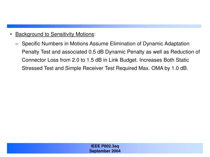
Background to Sensitivity Motions: • Specific Numbers in Motions Assume Elimination of Dynamic Adaptation Penalty Test and associated 0.5 dB Dynamic Penalty as well as Reduction of Connector Loss from 2.0 to 1.5 dB in Link Budget. Increases Both Static Stressed Test and Simple Receiver Test Required Max. OMA by 1.0 dB.
Motion x • Motion: • Adopt Following Parameters for Static Stressed Sensitivity Test in D1.0 in Table 68-4 • Maximum OMA of –6.6 dBm (TBC) • Clock Sinusoidal Jitter Frequency of 40 MHz • Clock Sinusoidal Jitter Amplitude of 0.1 UI • Remove References to Sinusoidal Interferer Parameters in Table 68-4 • Add Line in Table 68-4 for Optical Signal to Noise Ratio of Stressed Sensitivity Test Compliance Signal with Value TBD. • Moved: Lew Aronson Second:
Motion x • Motion: • For Draft D1.0 : • Adopt 52.9.5 For OMA Measurement at TP2 • Define OMA Measurement of TP3 Compliance Signal With Same Method But With Recommended Square Wave Test Pattern with 10 ‘1’s and 10 ‘0’s. • Define OSNR Measurement of TP3 Compliance Signal With Same 10 bit Square Wave and Histogram Measurements of 0 and 1 Levels To Fit Gaussian Noise Distributions. • Moved: Lew Aronson Second:
Motion x • Motion: • Pursue Development of a Set of 3 ISI Impairments For the Stressed Receiver Sensitivity Test Consisting of Pre-Cursor, Post-Cursor and Quasi Symmetrical Impulse Responses. • Define ISI Impairments Using A Set of Up to 5 Impulse Peaks with Single Uniform Time Spacing, an Effective Pulse Response, and a Maximum PSR Metric From popescu_1_0904 For The Difference Between the Compliance Signal and The Defined ISI Impairments. • Not Use PIE-L Metrics in Evaluating Suitability of ISI Impairments in the Stressed and Simple Sensitivity Tests • To Assume Transmitter Pulse Responses of Not Less Than 47 ps Rise/Fall Times in Combination with The Channel Model in the Development of the TP3 Compliance Signal. • Moved: Lew Aronson Second: