Download
1 / 67
710 likes | 1.63k Vues
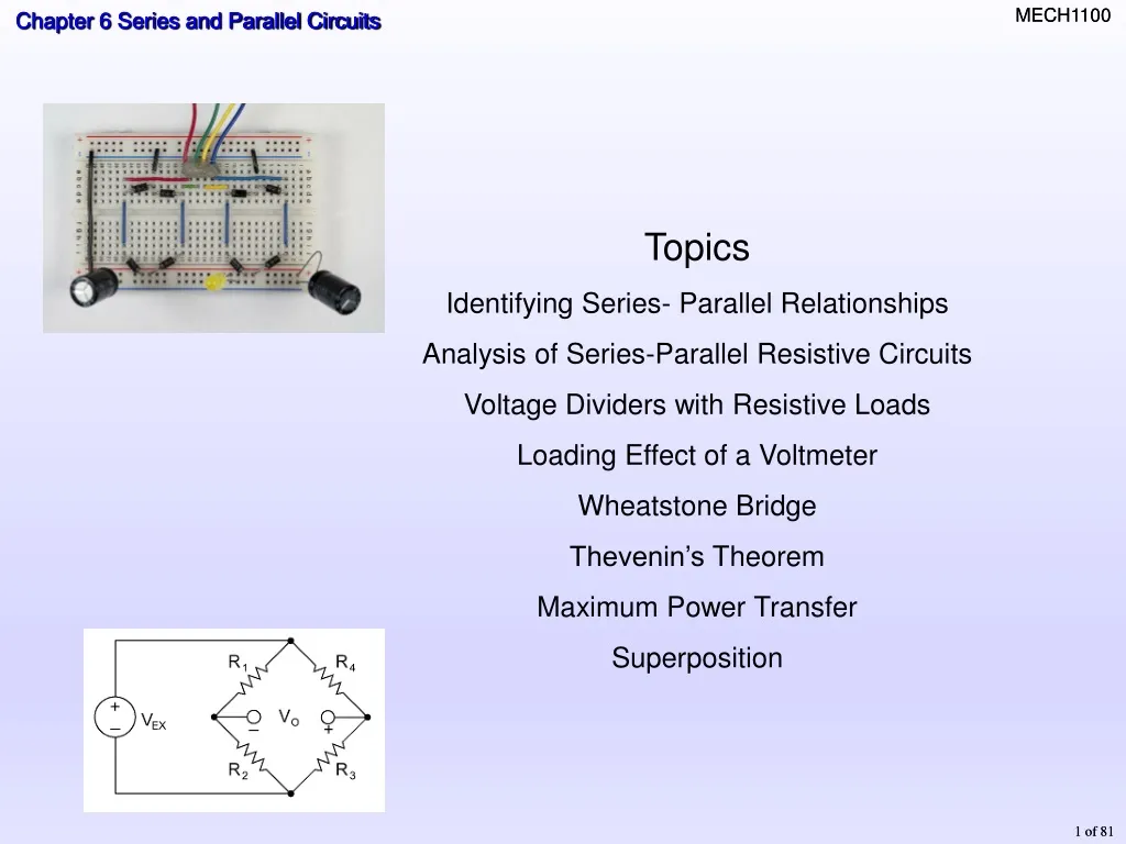
Topics Identifying Series- Parallel Relationships Analysis of Series-Parallel Resistive Circuits Voltage Dividers with Resistive Loads Loading Effect of a Voltmeter Wheatstone Bridge Thevenin’s Theorem Maximum Power Transfer Superposition. Identifying series-parallel relationships.

E N D
Topics Identifying Series- Parallel Relationships Analysis of Series-Parallel Resistive Circuits Voltage Dividers with Resistive Loads Loading Effect of a Voltmeter Wheatstone Bridge Thevenin’s Theorem Maximum Power Transfer Superposition
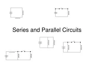
Identifying series-parallel relationships Most practical circuits have combinations of series and parallel components. From Chapters 4 and 5 Components that are connected in series will share a common path. Components that are connected in parallel will be connected across the same two nodes. 1 2
Combination circuits Circuits containing both series and parallel circuits are called COMBINATION circuits You can frequently simplify analysis by combining series and parallel components. Solve by forming the simplest equivalent circuit possible. An equivalent circuitis one that : hascharacteristics that are electricallythe same as another circuit is generally simpler.
Equivalent circuits is equivalent to There are no electrical measurements that can distinguish between the boxes.
is equivalent to Equivalent circuits Another example: There are no electrical measurements that can distinguish between the boxes.
is equivalent to is equivalent to There are no electrical measurements that can distinguish between thethreeboxes. Equivalent circuits
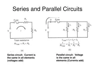
What Do We Know • For Series Circuits: • Current at all points is the • IT = IR1 = IR2 • Voltage across each resistor • VT = V1 + V2 • For Parallel Circuit • Current • IT = IR1 + IR2 • Voltage at all nodes is the • VT = V1 = V2 same drops divides across each resistor in the branch same
Seven Step Process for Solving a Combination Circuit • Simplify the circuit to a series circuit by finding the effective equivalent resistance (REQ) of each parallel section in the circuit. Redraw the circuit each time it is simplified. • Calculate the total resistance (RT) of the circuit by adding all REQ’s to the other series resistances. • Calculate the total current (IT) using RT in Ohm’s law. • Calculate the voltage drop across any series resistances or REQ’s using Ohm’s law. • Calculate the branch currents in all parallel sections of the circuit using the voltage drop across REQ and Ohm’s law. • Use the branch currents and resistance values to calculate the voltage of the parallel resistances. • Make a summary of the voltage drops and currents for each resistance to make sure they total correctly.
R6 is added to the circuit in parallel with the series combination of R1 and R4.
Draw the schematic for this circuit board and give the equation for the relationship of the resistor branches
6 4 10 Ω
10 10 5 Ω
IT 5 30 15 50 Ω IT = 2 amps
Kirchoff’s current law What are the readings for node A?
Loaded voltage divider The voltage-divider equation was developed for a series circuit. Recall that the output voltage is given by + A A voltage-divider with a resistive load forms a combination (parallel) circuit. The voltage divider is said to be LOADED. The loading reduces the total resistance from node A to ground.
Loaded voltage divider What is the voltage across R3? A Form an equivalent series circuit by combining R2 and R3; then apply the voltage-divider formula to the equivalent circuit: 8.10 V
Stiff voltage divider • A stiff voltage-divider is one in which the loaded voltage is nearly the same as the no-load voltage. • To accomplish this, the load current must be small compared to the bleeder current (or RL is large compared to the divider resistors).
Stiff voltage divider Given: R1 = R2 = 1.0 kW, What value of RL will make the divider a stiff voltage divider? What fraction of the unloaded voltage is the loaded voltage? Rule of Thumb:RL = R2*10; Thus: RL should be 10 kW or greater. This is 95% of the unloaded voltage.
Wheatstone bridge Voltage Divider 1 Voltage Divider 2
Wheatstone Bridge V1=V2 I1=I3 V3=V4 I2=I4
4.04 V Wheatstone Bridge • The Wheatstone bridge consists of: • a dc voltage source and • four resistive arms forming two voltage dividers. • The output is taken between the dividers. • Frequently, one of the bridge resistors is adjustable. (R2) .
Balanced Wheatstone Bridge When the bridge is balanced, the output voltage is zero The products of resistances in the opposite diagonal arms are equal.
Wheatstone bridge What is the value of R2 if the bridge is balanced? 330 W 470 W 12 V 385 W 270 W
Measuring a physical parameter using a transducer. Unbalanced Wheatstone Bridge • Unbalance occurs when VOUT ≠ 0 • Used to measure • Mechanical Strain • Temperature • Pressure • VOUT is converted to a digital output indicating the value of the reading.
10 10 10 10 10 Using the Thermistor chart, what is VOUT when the temperature is 50o C VA=8.8v VB=6.0v VA-B=2.8v
Thevenin’s theorem • Any two-terminal, resistive circuit can be replaced with a simple equivalent circuit when viewed from two output terminals. • Equivalent Voltage (VTH) is the “No Load” voltage between the two output terminals. • Equivalent Resistance (RTH) is the total resistance appearing between two output terminals • Terminal equivalency
Remember, the load resistor has no affect on the Thevenin parameters. Thevenin’s theorem What is the Thevenin voltage for the circuit? 8.76 V Output terminals
Remember, the load resistor has no affect on the Thevenin parameters. Thevenin’s theorem What is the Thevenin resistance for the circuit? 7.30 kW Output terminals SHORTED
Thevenin’s equivalent depends on the output terminals from which the circuit is viewed.
Thevenin’s equivalent depends on the output terminals from which the circuit is viewed.
Thevenin’s theorem and Wheatstone Bridge • Thevenin’s theorem is useful for solving the Wheatstone bridge. • Thevenize the bridge into two Thevenin circuits • A to ground • B to ground. • Resistance between point A and ground is R1||R3 • Resistance between B to ground is R2||R4. • The voltage on each side of the bridge is found using the voltage divider rule.
Thevenin’s theorem and Wheatstone Bridge Remove RL to make an open circuit between A & B Calculate R1||R3 = Calculate R2||R4 = Calculate the voltage from A to ground Calculate the voltage from B to ground Draw the Thevenin circuits for each of the bridge 165 W 179 W 7.5 V 6.88 V