Download
1 / 62
630 likes | 826 Vues
Multicore Applications Team. KeyStone C66x Multicore SoC Overview. KeyStone Overview. KeyStone Architecture CorePac & Memory Subsystem Interfaces and Peripherals Coprocessors and Accelerators Debug. Enhanced DSP core. Performance improvement. 100% upward object code compatible

E N D
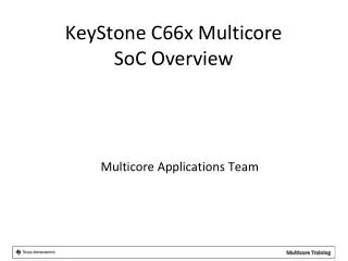
Multicore Applications Team KeyStone C66x Multicore SoC Overview
KeyStone Overview KeyStone Architecture CorePac & Memory Subsystem Interfaces and Peripherals Coprocessors and Accelerators Debug
Enhanced DSP core Performance improvement 100% upward object code compatible 4x performance improvement for multiply operation 32 16-bit MACs Improved support for complex arithmetic and matrixcomputation C66x ISA 100% upward object code compatible with C64x, C64x+, C67x and c67x+ Best of fixed-point and floating-point architecture for better system performance and faster time-to-market. 2x registers Enhanced floating-point add capabilities SPLOOP and 16-bit instructions for smaller code size Flexible level one memory architecture iDMA for rapid data transfers between local memories C64x+ C674x C67x+ Native instructions for IEEE 754, SP&DP Advanced VLIW architecture C67x Advanced fixed-point instructions Four 16-bit or eight 8-bit MACs Two-level cache C64x FLOATING-POINT VALUE FIXED-POINT VALUE Preliminary Information under NDA - subject to change
KeyStone Device Features Application-Specific Memory Subsystem Coprocessors MSM 64-Bit SRAM DDR3 EMIF MSMC Debug & Trace Boot ROM Semaphore C66x™ CorePac Power Management PLL L1 L1 P-Cache D-Cache x3 L2 Cache EDMA 1 to 8 Cores @ up to 1.25 GHz x3 HyperLink TeraNet Multicore Navigator Queue Packet Manager DMA x4 t x2 - O n e h s / o T I n c r i I t Security c r t R e C P i h a i e e f O c h Accelerator i A c w 2 I S i I h c I t l t C t e U p R S i O p E p w P S S A Packet S Accelerator I I x2 M G Network Coprocessor S • C66x CorePac • 1 to 8 C66x Fixed/Floating-Point CorePac DSP Cores at up to 1.25 GHz • Backward-compatible with C64x+ and C67x+ cores • Fixed and Floating Point Operations • RSA instruction set extensions • Chip-rate processing (downlink & uplink) • Reed-Muller decoding (CorePac 1 and 2 only) • Memory Subsystem • Up to 1 MB Local L2 memory per core • Up to 4 MB Multicore Shared Memory (MSM) • Multicore Shared Memory Controller (MSMC) • Boot ROM, DDR3-1600 MHz (64-bit) • Application-Specific Coprocessors • 2x TCP3d: Turbo Decoder • TCP3e: Turbo Encoder • 2x FFT (FFT/IFFT and DFT/IDFT) Coprocessor • 4x VCP2 for voice channel decoding • Multicore Navigator • Queue Manager • Packet DMA • Network Coprocessor • Packet Accelerator • Security Accelerator • Interfaces • High-speed Hyperlink bus • 4x Serial RapidIO Rev 2.1 • 2x 10/100/1000 Ethernet SGMII ports w/ embedded switch • 2x PCIe Generation II • Six-lane Antenna Interface (AIF2) for Wireless Applications • WCDMA, WiMAX, LTE, GSM, TD-SCDMA, TD-LTE • Up to 6.144-Gbps • Additional Serials: I2C, SPI, GPIO, UART • Embedded Trace Buffer (ETB) & System Trace Buffer (STB) • Smart Reflex Enabled • 40 nm High-Performance Process
1 to 8 C66x CorePac DSP Cores operating at up to 1.25 GHz Fixed and Floating Point Operations Code compatible with other C64x+ and C67x+ devices L1 Memory can be partitioned as cache or SRAM 32KB L1P per core 32KB L1D per core Error Detection for L1P Memory Protection Dedicated and Shared L2 Memory 512 KB to 1 MB Local L2 per core 2 to 4 MB Multicore Shared Memory (MSM) Multicore Shared Memory Controller (MSMC) Error detection and correction for all L2 memory MSM available to all cores and can be either program or data Boot ROM CorePac & Memory Subsystem Application-Specific Memory Subsystem Coprocessors MSM 64-Bit SRAM DDR3 EMIF MSMC Debug & Trace Boot ROM Semaphore C66x™ CorePac Power Management PLL L1 L1 P-Cache D-Cache x3 L2 Memory (cache/RAM) EDMA 1 to 8 Cores @ up to 1.25 GHz x3 TeraNet HyperLink Multicore Navigator Queue Packet Manager DMA - t x4 O x2 n e s h / T o I r n i I c t c R e C r P h t i Security a e O f i h e c A i c S I 2 I w i Accelerator I c t h l t C U R e p i t O S p P w p E S S A S Packet Accelerator I I M x2 G S Network Coprocessor CorePac & Memory Subsystem
Memory Expansion Application-Specific Memory Subsystem Coprocessors MSM 64-Bit SRAM DDR3 EMIF MSMC Debug & Trace Boot ROM Semaphore C66x™ CorePac Power Management PLL L1 L1 P-Cache D-Cache x3 L2 SRAM EDMA 1 to 8 Cores @ up to 1.25 GHz x3 TeraNet HyperLink Multicore Navigator Queue Packet Manager DMA - t x4 O x2 n e s h / T o I r n i I c t c R e C r P h t i Security a e O f i h e c A i c S I 2 I w i Accelerator I c t h l t C U R e p i t O S p P w p E S S A S Packet Accelerator I I M x2 G S Network Coprocessor CorePac & Memory Subsystem Memory Expansion • Multicore Shared Memory Controller (MSMC) • Arbitrates CorePac and SoC master access to shared memory • Provides a direct connection to the DDR3 EMIF • Provides CorePac access to coprocessors and IO peripherals • Memory protection and address extension to 64 GB (36 bits) • Provides multi-stream pre-fetching capability • DDR3 External Memory Interface (EMIF) • Support for 1x 16-bit, 1x 32-bit, and 1x 64-bit modes • Supports up to 1600 MHz • Supports power down of unused pins when using 16-bit or 32-bit width • Support for 8 GB memory address • Error detection and correction • EMIF-16 (Media Applications Only) • Three modes: • Synchronized SRAM • NAND flash • NOR flash • Can be used to connect asynchronous memory (e.g., NAND flash) up to 256 MB.
Multicore Navigator Application-Specific Memory Subsystem Coprocessors MSM 64-Bit SRAM DDR3 EMIF MSMC Debug & Trace Boot ROM Semaphore C66x™ CorePac Power Management PLL L1 L1 P-Cache D-Cache x3 L2 SRAM EDMA 1 to 8 Cores @ up to 1.25 GHz x3 TeraNet HyperLink Multicore Navigator Queue Packet Manager DMA - t x4 O x2 n e s h / T o I r n i I c t c R e C r P h t i Security a e O f i h e c A i c S I 2 I w i Accelerator I c t h l t C U R e p i t O S p P w p E S S A S Packet Accelerator I I M x2 G S Network Coprocessor CorePac & Memory Subsystem Memory Expansion Multicore Navigator • Queue Manager and Packet DMA • Low-overhead processing and routing of packet traffic • Simplified resource management • Effective inter-processor communications • Abstracts physical implementation from application host software • Virtualization to enable dynamic load balancing and provide seamless access to resources on different cores • 8K hardware queues and 16K descriptors • More descriptors can reside in any shared memory • 10 Gbps pre-fetching capability
Network Coprocessor Application-Specific Memory Subsystem Coprocessors MSM 64-Bit SRAM DDR3 EMIF MSMC Debug & Trace Boot ROM Semaphore C66x™ CorePac Power Management PLL L1 L1 P-Cache D-Cache x3 L2 SRAM EDMA 1 to 8 Cores @ up to 1.25 GHz x3 TeraNet HyperLink Multicore Navigator Queue Packet Manager DMA - t x4 O x2 n e s h / T o I r n i I c t c R e C r P h t i Security a e O f i h e c A i c S I 2 I w i Accelerator I c t h l t C U R e p i t O S p P w p E S S A S Packet Accelerator I I M x2 G S Network Coprocessor CorePac & Memory Subsystem Memory Expansion Multicore Navigator Network Coprocessor • Packet Accelerator (PA) • Support for single or multiple IP addresses • 1 Gbps wire-speed throughput at 1.5 Mpps • UDP Checksum processing • IPSec ESP and AH tunnels with fast path fully offloaded • L2 support: Ethernet, Ethertype, and VLAN • L3/L4 Support: IPv4/IPv6 and UDP port-based raw Ethernet or IPv4/6 and SCTP port-based routing • Multicast to multiple queues • QoS capability: Per channel/flow to individual queue towards DSP cores and support for TX traffic shaping per device • Security Accelerator (SA) • Support for IPSec, SRTP, 3GPP and WiMAX Air Interface, and SSL/TLS security • Support for simultaneous wire-speed security processing on 1 Gbps Ethernet transmit and receive traffic. • Encryption Modes: ECB, CBC, CTR, F8, A5/3, CCM, GCM, HMAC, CMAC, and GMAC • Encryption Algorithms: AES, DES, 3DES, Kasumi, SNOW 3g, SHA-1, SHA-2, and MD5
External Interfaces SGMII allows two 10/100/1000 Ethernet interfaces Four high-bandwidth Serial RapidIO (SRIO) lanes for inter-DSP applications SPI for boot operations UART for development/testing Two PCIe at 5 Gbps I2C for EPROM at 400 Kbps Application-specific Interfaces: Antenna Interface 2 (AIF2) for wireless applications Telecommunications Serial Port (TSIP) x2 for media applications Application-Specific Memory Subsystem Coprocessors MSM 64-Bit SRAM DDR3 EMIF MSMC Debug & Trace Boot ROM Semaphore C66x™ CorePac Power Management PLL L1 L1 P-Cache D-Cache x3 L2 SRAM EDMA 1 to 8 Cores @ up to 1.25 GHz x3 TeraNet HyperLink Multicore Navigator Queue Packet Manager DMA - t x4 O x2 n e s h / T o I r n i I c t c R e C r P h t i Security a e O f i h e c A i c S I 2 I w i Accelerator I c t h l t C U R e p i t O S p P w p E S S A S Packet Accelerator I I M x2 G S Network Coprocessor CorePac & Memory Subsystem Memory Expansion Multicore Navigator Network Coprocessor External Interfaces
TeraNet is a process controller Channel Controller Transfer Controller TeraNet provides a configured way – within hardware – to manage traffic queues and ensure priority jobs are getting accomplished while minimizing the involvement of the DSP cores. TeraNet facilitates high-bandwidth communications between CorePac cores, subsystems, peripherals, and memory. TeraNet Switch Fabric Application-Specific Memory Subsystem Coprocessors MSM 64-Bit SRAM DDR3 EMIF MSMC Debug & Trace Boot ROM Semaphore C66x™ CorePac Power Management PLL L1 L1 P-Cache D-Cache x3 L2 Cache EDMA 1 to 8 Cores @ up to 1.25 GHz x3 TeraNet HyperLink Multicore Navigator Queue Packet Manager DMA - t x4 O x2 n e s h / T o I r n i I c t c R e C r P h t i Security a e O f i h e c A i c S I 2 I w i Accelerator I c t h l t C U R e p i t O S p P w p E S S A S Packet Accelerator I I M x2 G S Network Coprocessor CorePac & Memory Subsystem Memory Expansion Multicore Navigator Network Coprocessor External Interfaces TeraNet Switch Fabric
Diagnostic Enhancements Embedded Trace Buffers (ETB) enhance the diagnostic capabilities of the CorePac. CP Monitor enables diagnostic capabilities on data traffic through the TeraNet switch fabric. Automatic statistics collection and exporting (non-intrusive) Monitor individual events for better debugging Monitor transactions to both memory end point and MMRs (memory mapped Regi) Configurable monitor filtering capability based on address and transaction type Application-Specific Memory Subsystem Coprocessors MSM 64-Bit SRAM DDR3 EMIF MSMC Debug & Trace Boot ROM Semaphore C66x™ CorePac Power Management PLL L1 L1 P-Cache D-Cache x3 L2 Cache EDMA 1 to 8 Cores @ up to 1.25 GHz x3 TeraNet HyperLink Multicore Navigator Queue Packet Manager DMA - t x4 O x2 n e s h / T o I r n i I c t c R e C r P h t i Security a e O f i h e c A i c S I 2 I w i Accelerator I c t h l t C U R e p i t O S p P w p E S S A S Packet Accelerator I I M x2 G S Network Coprocessor CorePac & Memory Subsystem Memory Expansion Multicore Navigator Network Coprocessor External Interfaces TeraNet Switch Fabric Diagnostic Enhancements
HyperLink Bus Provides the capability to expand the C66x to include hardware acceleration or other auxiliary processors Four lanes with up to 12.5 Gbps per lane Application-Specific Memory Subsystem Coprocessors MSM 64-Bit SRAM DDR3 EMIF MSMC Debug & Trace Boot ROM Semaphore C66x™ CorePac Power Management PLL L1 L1 P-Cache D-Cache x3 L2 Cache EDMA 1 to 8 Cores @ up to 1.25 GHz x3 TeraNet HyperLink Multicore Navigator Queue Packet Manager DMA - t x4 O x2 n e s h / T o I r n i I c t c R e C r P h t i Security a e O f i h e c A i c S I 2 I w i Accelerator I c t h l t C U R e p i t O S p P w p E S S A S Packet Accelerator I I M x2 G S Network Coprocessor CorePac & Memory Subsystem Memory Expansion Multicore Navigator Network Coprocessor External Interfaces TeraNet Switch Fabric Diagnostic Enhancements HyperLink Bus
Miscellaneous Elements Semaphore2 provides atomic access to shared chip-level resources. Boot ROM Power Management Eight 64-bit timers Three on-chip PLLs: PLL1 for CorePacs PLL2 for DDR3 PLL3 for Packet Acceleration Three EDMA Application-Specific Memory Subsystem Coprocessors MSM 64-Bit SRAM DDR3 EMIF MSMC Debug & Trace Boot ROM Semaphore C66x™ CorePac Power Management PLL L1 L1 P-Cache D-Cache x3 L2 Cache EDMA 1 to 8 Cores @ up to 1.25 GHz x3 TeraNet HyperLink Multicore Navigator Queue Packet Manager DMA - t x4 O x2 n e s h / T o I r n i I c t c R e C r P h t i Security a e O f i h e c A i c S I 2 I w i Accelerator I c t h l t C U R e p i t O S p P w p E S S A S Packet Accelerator I I M x2 G S Network Coprocessor CorePac & Memory Subsystem Memory Expansion Multicore Navigator Network Coprocessor External Interfaces TeraNet Switch Fabric Diagnostic Enhancements HyperLink Bus Miscellaneous
Device-Specific: Wireless Applications KeyStone Device Architecture for Wireless Applications Memory Subsystem Coprocessors 2MB 64-Bit MSM DDR3 EMIF SRAM MSMC RSA RSA Debug & Trace x2 VCP2 x4 Boot ROM Semaphore TCP3d C66x™ x2 CorePac Power Management TCP3e PLL 32KB L1 32KB L1 FFTC x2 P-Cache D-Cache x3 1024KB L2 Cache EDMA 4 Cores @ 1.0 GHz / 1.2 GHz x3 HyperLink TeraNet Multicore Navigator Queue Packet Manager DMA t x4 x2 x6 e s h T r n I c R e C r P t h O e i 2 h e A 2 c I S I w I F t h t C U R i I t O S P A w E S S Packet Accelerator I I M 2 ´ G S Network Coprocessor CorePac & Memory Subsystem Memory Expansion Multicore Navigator Network Coprocessor External Interfaces TeraNet Switch Fabric Diagnostic Enhancements HyperLink Bus Miscellaneous BCP Application-Specific Coprocessors Device-Specific (Wireless Apps) • Wireless-specific Coprocessors • FFTC • TCP3 Decoder/Encoder • VCP2 • BCP • Wireless-specific Interfaces: AIF2 x6 • Characteristics • Package Size: 24x24 • Process Node: 40nm • Pin Count: 841 • Core Voltage: 0.9-1.1 V • 2x Rake Search Accelerator (RSA) Security Accelerator
Device-Specific: Media Applications KeyStone Device Architecture for Media Applications Memory Subsystem 4MB 64-Bit MSM DDR3 EMIF SRAM MSMC Debug & Trace Boot ROM Semaphore C66x™ CorePac Power Management PLL 32KB L1 32KB L1 P-Cache D-Cache x3 512KB L2 Cache EDMA 1 to 8 Cores @ up to 1.25 GHz x3 HyperLink TeraNet TeraNet Multicore Navigator Queue Packet Manager DMA t x4 x2 x2 6 e h T 1 O n I c R C r I Security P t h F O e P i P e I A 2 c I S Accelerator I I w I h t M G C U S R i t S E P w T E S S Packet Accelerator I I M x2 G S Network Coprocessor CorePac & Memory Subsystem Memory Expansion Multicore Navigator Network Coprocessor External Interfaces TeraNet Switch Fabric Diagnostic Enhancements HyperLink Bus Miscellaneous Application-Specific Coprocessors Device-Specific (Media Apps) • Media-specific Interfaces • TSIP x2 • EMIF 16 (EMIF-A) • Characteristics • Package Size: 24x24 • Process Node: 40nm • Pin Count: 841 • Core Voltage: 0.9-1.1 V
KeyStone C6655/57: Device Features C6655/57 Memory Subsystem 1MB MSM 32-Bit SRAM DDR3 EMIF MSMC Debug & Trace Boot ROM 2nd core, C6657 only Semaphore C66x™ Timers CorePac Security / Key Manager Coprocessors Power Management 32KB L1 32KB L1 TCP3d P-Cache D-Cache PLL 1024KB L2 Cache x2 VCP2 x2 EDMA 1 or 2 Cores @ up to 1.25 GHz TeraNet HyperLink Multicore Navigator Queue Packet Manager DMA x2 x2 x2 x4 6 Ethernet O 1 P P T I F I P O S MAC I P P R e I2C I I M U B S G A C R E c U S P M SGMII • C66x CorePac • C6655: One C66x CorePac DSP Coreat 1.0 or 1.25 GHz • C6657: Two C66x CorePac DSP Cores at 0.85, 1.0, or 1.25 GHz • Fixed and Floating Point Operations • Backward-compatible with C64x+ and C67x+ cores • Memory Subsystem • 1 MB Local L2 memory per core • Multicore Shared Memory Controller (MSMC) • 32-bit DDR3 Interface • Hardware Coprocessors • Turbo Coprocessor Decoder (TCP3d) • 2x Viterbi Coprocessors (VCP2) • Multicore Navigator • Queue Manager (8192 hardware queues) • Packet-based DMA • Interfaces • High-speed Hyperlink bus • One 10/100/1000 Ethernet SGMII port • 4x Serial RapidIO (SRIO) Rev 2.1 • 2x PCIeGen2 • 2x Multichannel Buffered Serial Ports (McBSP) • One Asynchronous Memory Interface (EMIF16) • Additional Serials: SPI, I2C, UPP, GPIO, UART • Embedded Trace Buffer (ETB) andSystem Trace Buffer (STB) • Smart Reflex Enabled • 40 nm High-Performance Process
KeyStone C6654: Power Optimized C6654 • C66x CorePac • C6654: One CorePac DSP Core at 850 MHz • Fixed and Floating Point Operations • Backward compatible with C64x+ and C67x+ cores • Memory Subsystem • 1 MB Local L2 memory • Multicore Shared Memory Controller (MSMC) • 32-bit DDR3 Interface • Multicore Navigator • Queue Manager (8192 hardware queues) • Packet-based DMA • Interfaces • One 10/100/1000 Ethernet SGMII port • 2x PCIeGen2 • 2x Multichannel Buffered Serial Ports (McBSP) • One Asynchronous Memory Interface (EMIF16) • Additional Serials: SPI, I2C, UPP, GPIO, UART • Embedded Trace Buffer (ETB) andSystem Trace Buffer (STB) • Smart Reflex Enabled • 40 nm High-Performance Process Memory Subsystem 32-Bit MSMC DDR3 EMIF Debug & Trace Boot ROM Semaphore C66x™ Timers CorePac Security / Key Manager Power Management 32KB L1 32KB L1 P-Cache D-Cache PLL 1024KB L2 Cache x2 EDMA 1 Core @ 850 MHz TeraNet Multicore Navigator Queue Packet Manager DMA x2 x2 x2 6 Ethernet O 1 P P T I F I P S MAC I P P R e I2C I M U B S G A C E c U P M SGMII
KeyStone Overview KeyStone Architecture CorePac & Memory Subsystem Interfaces and Peripherals Coprocessors and Accelerators Debug
CorePac 0 CorePac 1 CorePac 2 CorePac 3 XMC XMC XMC XMC MPAX MPAX MPAX MPAX 256 256 256 256 CorePac CorePac CorePac CorePac Slave Port Slave Port Slave Port Slave Port MSMC Datapath System Memory Slave Port Protection Teranet Arbitration and for shared Extension SRAM 256 256 Unit ( SMS ) ( MPAX ) Shared RAM , 2048 KB Memory 256 System Slave Port for external memory Protection EDC and Extension 256 Unit 256 ( MPAX ) ( SES ) MSMC Core MSMC EMIF MSMC System Master Port Master Port events 256 256 EMIF – 64 bit TeraNet DDR 3 MSMC Block Diagram
C66x TeraNet Data Connections TC7 TC4 TC3 TC9 TC2 TC5 TC8 TC6 TC1 TC0 M M M M M M M M M M DebugSS M HyperLink S MSMC DDR3 S M CPUCLK/2 256bit TeraNet S Shared L2 DDR3 HyperLink M M S S S S TPCC 16ch QDMA EDMA_0 • C6616 TeraNet facilitates high Bandwidth communication links between DSP cores, subsystems, peripherals, and memories. • TeraNet supports parallel orthogonal communication links • In order to evaluate the potential communication link throughput, consider the peripheral bit-width and the speed of TeraNet • Please note that while most of the communication links are possible, some of them are not, or are supported by particular Transfer Controllers. Details are provided in the C6616 Data Manual XMC S L2 0-3 M S Core M SRIO M S Core M S Core M M Network Coprocessor M SRIO S TPCC 64ch QDMA S TCP3e_W/R TPCC 64ch QDMA S TCP3d EDMA_1,2 S TCP3d CPUCLK/3 128bit TeraNet S TAC_BE TAC_FE M S RAC_FE RAC_BE0,1 M RAC_FE S RAC_BE0,1 M FFTC / PktDMA M FFTC / PktDMA M S VCP2 (x4) VCP2 (x4) S VCP2 (x4) S AIF / PktDMA M VCP2 (x4) S QM_SS M QMSS S PCIe M S PCIe …
Multicore Navigator Overview Multicore Navigator Purpose - seamless inter-core communications between cores, IP and peripherals. “Fire and forget” Supports synchronization between cores, move data between cores, move data to and from peripherals Consists of a Queue Manager and multiple, dedicated Packet DMA engines Data transfer architecture designed to minimize host interaction while maximizing memory and bus efficiency Move Descriptors and buffers (or pointers to) between different parts of the Chip Navigator hardware: Queue Manager Subsystem (QMSS) Multiple Packet DMA (PKTDMA)
Queue Manager Subsystem (QMSS) • Features: • 8192 total hardware queues • Up to 20 Memory regions for descriptor storage (LL2, MSMC, DDR) • Up to 2 Linking RAMs for queue linking/management • Up to 16K descriptors can be handled by internal Link RAM. • Second Link RAM can be placed in L2 or DDR. • Up to 512K descriptors supported in total. • Can copy descriptor pointers of transferred data to destination core’s local memory to reduce access latency • Major hardware components: • Queue Manager • PKTDMA (Infrastructure DMA) • 2 PDSPs (Packed Data Structure Processors) for: • Descriptor Accumulation / Queue Monitoring • Load Balancing and Traffic Shaping • Interrupt Distributor (INTD) module
Packet DMA Topology FFTC (B) Queue Manager Subsystem SRIO FFTC (A) Queue Manager PKTDMA 0 1 PKTDMA 2 PKTDMA 3 4 5 . . . 8192 AIF Network Coprocessor PKTDMA PKTDMA PKTDMA • Multiple Packet DMA instances in KeyStone devices: • QMSS, PA and SRIO instances for all KeyStone devices. • AIF2 and FFTC (A and B) instances are only in KeyStone devices for wireless applications. • Transfer engine interface between peripherals/accelerators and QMSS • Autonomously determines memory buffers to fill and queues to post based on initial setup and buffer descriptor
Queues/Descriptors/Packets Queue Host Packet PTR Descriptor PTR PTR Length PTR ... Data . . . Host Buffer Descriptor PTR PTR Length Data ... Monolithic Descriptor Length ... Data
XMC – External Memory Controller The XMC is responsible for: Address extension/translation Memory protection for addresses outside C66x Shared memory access path Cache and Pre-fetch support User Control of XMC: MPAX registers – Memory Protection and Extension Registers MAR registers – Memory Attributes registers Each core has its own set of MPAX and MAR registers !
The MPAX Registers • MPAX = Memory Protection and Extension Registers • Translate between physical and logical address • 16 registers (64 bits each) control (up to) 16 memory segments. • Each register translates logical memory into physical memory for the segment. • Segment definition in the MPAX registers: • Segment size – 5 bits – power of 2, smallest segment size 4K, up to 4GB • Logical base address – • Physical (replacement address) base • Permission – access type allowed in this address range
The MAR Registers • MAR = Memory Attributes Registers • 256 registers (32 bits each) control 256 memory segments. • Each segment size is 4M Bytes, from logical address 0x00000000 to address 0xffffffff • The first 16 registers are read-only. They control the internal memory of the core. • Each register controls the cache-ability of the segment (bit 0) and the pre-fetch-ability (bit 3). All other bits are reserved and set to 0. • All MAR bits are set to zero after reset.
KeyStone Overview KeyStone Architecture CorePac & Memory Subsystem Interfaces and Peripherals Coprocessors and Accelerators Debug
EDMA Three EDMA Channel Controllers: • One controller in CPU/2 domain: • Two transfer controllers/queues with 1KB channel buffer • Eight QDMA channels • 16 interrupt channels • 128 PaRAM entries • Two controllers in CPU/3 domain; Each includes the following: • Four transfer controllers/queues with 1KB or 512B channel buffer • Eight QDMA channels • 64 interrupt channels • 512 PaRAM entries • Flexible transfer definition • Linking mechanism allows automatic PaRAM set update. • Chaining allows multiple transfers to execute with one event. • Interrupt generation • Transfer completion • Error conditions 510 511
Interfaces Overview • Two SGMII ports with embedded switch • Supports IEEE1588 timing over Ethernet • Supports 1G/100 Mbps full duplex • Supports 10/100 Mbps half duplex • Inter-working with RapidIO message • Integrated with packet accelerator for efficient IPv6 support • Supports jumbo packets (9 Kb) • Three-port embedded Ethernet switch with packet forwarding • Reset isolation with SGMII ports and embedded ETH switch • HyperLink bus • Hardware hooks for analog device or customer ASIC • Application-Specific Interfaces • For Wireless Applications • Antenna Interface 2 (AIF2) • Multiple-standard support (WCDMA, LTE, WiMAX, GSM/Edge) • Generic packet interface (~12Gbits/sec ingress & egress) • Frame Sync module (adapted for WiMAX, LTE & GSM slots/frames/symbols boundaries) • Reset Isolation • For Media Gateway Applications • Telecommunications Serial Port (TSIP) • Two TSIP ports for interfacing TDM applications • Supports 2/4/8 lanes at 32.768/16.384/8.192 Mbps per lane & up to 1024 DS0s • Common Interfaces • One PCI Express (PCIe) Gen II port • Two lanes running at 5G Baud • Support for root complex (host) mode and end point mode • Single Virtual Channel (VC) and up to eight Traffic Classes (TC) • Hot plug • Universal Asynchronous Receiver/Transmitter (UART) • 2.4, 4.8, 9.6, 19.2, 38.4, 56, and 128 K baud rate • Serial Port Interface (SPI) • Operate at up to 66 MHz • Two-chip select • Master mode • Inter IC Control Module (I2C) • One for connecting EPROM (up to 4Mbit) • 400 Kbps throughput • Full 7-bit address field • General Purpose IO (GPIO) module • 16-bit operation • Can be configured as interrupt pin • Interrupt can select either rising edge or falling edge • Serial RapidIO (SRIO) • RapidIO 2.1 compliant • Four lanes @ 5 Gbps • 1.25/2.5/3.125/5 Gbps operation per lane • Configurable as four 1x, two 2x, or one 4x • Direct I/O and message passing (VBUSM slave) • Packet forwarding • Improved support for dual-ring daisy-chain • Reset isolation • Upgrades for inter-operation with packet accelerator
Ethernet Switch: Overview • 3-Port Ethernet Switch • Port 0: CPPI port • Port 1: SGMII 0 Port • Port 2: SGMII 1 Port • Ethernet Switch Modules • Two EMAC modules • Address Lookup Engine (ALE) module • Two Statistics modules • CPTS (Connect Port TS) module • The PA will be discussed later
Serial RapidIO (SRIO) • SRIO or RapidIO provides a 3-Layered architecture • Physical defines electrical characteristics, link flow control (CRC) • Transport defines addressing scheme (8b/16b device IDs) • Logical defines packet format and operational protocol • Two Basic Modes of Logical Layer Operation • DirectIO • Transmit Device needs knowledge of memory map of Receiving Device • Includes NREAD, NWRITE_R, NWRITE, SWRITE • Functional units: LSU, MAU, AMU • Message Passing • Transmit Device does not need knowledge of memory map of Receiving Device • Includes Type 11 Messages and Type 9 Packets • Functional units: TXU, RXU • Gen 2 Implementation – Supporting up to 5 Gbps
PCIe Interface • KeyStone incorporates a single PCIe interface with the following characteristics: • Two SERDES lanes running at 5 GBaud/2.5GBaud • Gen2 compliant • Three different operational modes (default defined by pin inputs at power up; can be overwritten by software): • Root Complex (RC) • End Point (EP) • Legacy End Point • Single Virtual Channel (VC) • Single Traffic Class (TC) • Maximum Payloads • Egress – 128 bytes • Ingress – 256 bytes • Configurable BAR filtering, IO filtering, and configuration filtering
HyperLink Bus Provides a high-speed interface between device interfaces through the TeraNet switch fabric. A single 4x bus operating at up to 12.5 Gbps per lane Connections are point-to-point. Device #2 Device #1 TeraNet Switch Fabric TeraNet Switch Fabric HyperLink
AIF 2.0 AIF2 is a peripheral module that supports data transfers between uplink and downlink baseband processors through a high-speed serial interface. AIF2 directly supports the following: WCDMA/FDD LTE FDD LTE TDD WiMax TD-SCDMA GSM/Edge (OBSAI only) Autonomous DMA PKTDMA or AIF VBUS Master More efficient data transfer for OFDM standards FIFO-based buffer provides flexible support for various sampling frequencies.
Other Peripherals & System Elements • EMIF16 • Used for booting, logging, announcement, etc. • Supports NAND flash memory, up to 256MB • Supports NOR flash up to 16MB • Supports asynchronous SRAM mode, up to 1MB • 64-Bit Timers • Total of 16 64-bit timers • One 64-bit timer per core is dedicated to serve as a watchdog (or may be used as a general purpose timer) • Eight 64-bit timers are shared for general purpose timers • Each 64-bit timer can be configured as two individual 32-bit timers • Timer Input/Output pins • Two timer Input pins • Two timer Output pins • Timer input pins can be used as GPI • Timer output pins can be used as GPO • On-Chip PLLs • Core • Packet & Security CoProcessors • DDR
Other Peripherals & System Elements (2) • Hardware Semaphores • Power Management • Support to assert NMI input for each core; Separate hardware pins for NMI and core selector • Support for local reset for each core; Separate hardware pins for local reset and core selector
Coprocessors and Accelerators KeyStone Architecture CorePac & Memory Subsystem Interfaces and Peripherals Coprocessors and Accelerators Debug
Network Coprocessor (NETCP) Overview The NETCP consists of the following modules: Packet Accelerator (PA) Deciphers and adds protocol headers to (and from) packets. Standard protocols and limited user’s defined protocol routing Security Accelerator (SA) Encrypts and decrypts packages Ethernet Subsystem Packet DMA (PKTDMA) Controller
Network Coprocessor (Logical) PKTDMA Queue Lookup Engine (IPSEC16 entries, 32 IP, 16 Ethernet) QMSS FIFO Queue Packet Accelerator Classify Pass 1 SRIO message RX CorePac 0 DSP 0 Classify Pass 2 DSP 0 DSP 0 Ethernet RX MAC RX PKTDMA SecurityAccelerator (cp_ace) Ingress Path Egress Path Ethernet TXMAC Modify Modify Ethernet TXMAC TX PKTDMA SRIO message TX
Session Identification Hardware lookup identifies the session. First-pass lookup: IPv4, IPv6, or Ethernet only 64 entries (16 Ethernet, 32 up to IPv6, 16 up to IPSec) IP with ESP or AH as next protocol and SPI Second-pass lookup: 8192 entries UDP, SCTP, etc. or proprietary up to 32-bit identifier within the first 128 bytes of the packet
FFTC • The FFTC is an accelerator that can be used to perform FFT and Inverse FFT (IFFT) on data. • The FFTC has been designed to be compatible with various OFDM-based wireless standards like WiMax and LTE. • The Packet DMA (PKTDMA) is used to move data in and out of the FFTC module. • The FFTC supports four input (Tx) queues that are serviced in a round-robin fashion. • Using the FFTC to perform computations that otherwise would have been done in software frees up CPU cycles for other tasks.
FFTC Features • Provides algorithms for both FFT and IFFT • Multiple block sizes: • Maximum 8192 • All LTE DFT (Long Term Evolution Discrete Fourier Transform) sizes • LTE 7.5 kHz frequency shift • 16 bits I/ 16 bits Q input and output – block floating point output • Dynamic and programmable scaling modes • Dynamic scaling mode returns block exponent • Support for left-right FFT shift (switch the left/right halves) • Support for variable FFT shift • For OFDM (Orthogonal Frequency Division Multiplexing) downlink, supports data format with DC subcarrier in the middle of the subcarriers • Support for cyclic prefix • Addition and removal • Any length supported • Three-buffer design allows for back-to-back computations • 128-bit, CPU/3, full-duplex VBUS connection • Input data scaling with shift eliminates the need for front-end digital AGC (Automatic Gain Control) • Output data scaling
Turbo CoProcessor 3 Decoder (TCP3D) LTE Bit Processing Per Transport Block Per Code Block De-Scrambling Channel De-interleaver LLR combining De-Rate Matching Soft Bits • LLR Data • Systematic • Parity 0 • Parity 1 TCP3D TB CRC Hard decision Decoded bits • TCP3D is a programmable peripheral for decoding of 3GPP (WCDMA, HSUPA, HSUPA+, TD_SCDMA), LTE, and WiMax turbo codes. • Turbo decoding is a part of bit processing.
TCP3D Key Features (1/2) • Supports 3GPP Rel-7 and older (WCDMA), LTE, and WiMAX turbo decoding • Native Code Rate: 1/3 • Radix 4 Binary and Duo-Binary MAP Decoders • Dual MAP decoders for non-contentious interleavers • Split decoder mode: TCP3D works as two independent, single MAP decoders • Max Star and Max log-map algorithms • Double Buffer input memory for lower latency transfers (except in split mode) • 128-bit data bus for reduced latency transfers • Input data bit width: 6 bits • Programmable hard decision bit ordering within a 128-bit word: 0-127 or 127-0 • Soft output information for systematic and parity bits: 8 bits • Extrinsic scaling per MAP for up to eight iterations (Both Max and Max Star)
TCP3D Key Features (2/2) • Block sizes supported: 40 to 8192 • Programmable sliding window sizes {16, 32, 48, 64, 96, 128} • Max number of iterations: 1 to 15 • Min number of iterations: 1 to 15 • SNR stopping criterion: 0 to 20 dB threshold • LTE CRC stopping criterion • LTE, WCDMA and WiMAX Hardware Interleaver Generators • Channel Quality Indication • Emulation support • Low DSP pre-processing load • Runs in parallel with CorePac • Targets base station environment
Turbo CoProcessor 3 Encoder (TCP3E) TCP3E = Turbo CoProcessor 3 Encoder No previous versions, but came out at same time as third version of decoder co-processor (TCP3D) Runs in parallel with DSP Performs Turbo Encoding for forward error correction of transmitted information (downlink for basestation) Adds redundant data to transmitted message Turbo Decoder in handset uses the redundant data to correct errors Often avoids retransmission due to a noisy channel Downlink Turbo Encoder (TCP3E) Turbo Decoder in Handset