Download
1 / 10
100 likes | 187 Vues
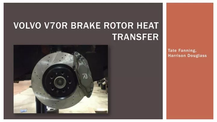
Volvo V70R Brake Rotor Heat Transfer. Tate Fanning, Harrison Douglass. Introduction.

E N D
Volvo V70R Brake Rotor Heat Transfer Tate Fanning, Harrison Douglass
Introduction • An vehicle's ability to effectively brake is critical to its performance; especially in racing situations. Brake performance is crippled if temperatures of the brake pads and rotors are too high. For this reason, the choice of material and design of brake components revolves around the brake's ability to not only brake effectively, but also to dissipate heat. It's is important that the brake system on each wheel dissipates heat at equal levels, therefore preventing overheating on one or two rotors and pads. This project evaluates heat transfer of brake rotors on each wheel in order to determine if changes are necessary to allow equal heat transfer on every wheel.
Problem Setup • Using the Volvo diagnostic system, individual brake rotor temperatures were monitored in real time on a laptop linked to the vehicle. The vehicle was accelerated to a speed of 80+ mph, at which point the brakes were applied with significant force such that each rotor reached a temperature greater than 100 °C. After reaching the prescribed temperature, the car was parked, and the brake rotors were allowed to cool. Temperature measurements of each rotor were collected in 15 second intervals for the first two minutes, after which the sampling period was increased to 30 seconds..
Assumptions • Brake rotors are subjected only to free and forced convection in air at 45 °F (280 K) and flowing at 0.5 m/s. • Brake rotors are made of carbon steel. • Each rotor can be modeled as a vertical plate of diameter 330 mm in a cross flow.
Solution and Procedure • The initial hot temperature of each brake rotor was first measured; these measurements were held as the surface temperatures for future calculations. • The Reynolds and Prandtl numbers for the cross flow (0.5 m/s at 280-300K) were found. • These numbers were considered to choose the proper correlation; based on the results and desired measure of accuracy, the Hilpert correlation was chosen. While this is less accurate the the Churchill correlation, it provides a good estimate and will allow us to see if the heat transfer rates are equal for each rotor. • The Nusslet number was found for each brake rotor. • The Grashof number for the flow was found and compared to the square of the Reynolds number. It was found that the Reynolds number squared was much larger than the Grashof number, which implies that free convection plays an insignificant role in the problem, so it was neglected. • The convection heat transfer coefficient was found and used to calculate the rate of heat transfer for each brake rotor. • The measured temperatures were then plotted. • See Appendix 2 for hand calculations.
Results • The rate of heat transfer was found to be equal for each front and each rear rotor respectively, but unequal between fronts and rear rotors. • The rate of heat transfer for the front rotors was found to be: 120.3992942 W/m. • The rate of heat transfer for the rear rotors was found to be: 163.4084291 W/m. • Each brake rotor seemed to cool at the same rate, as seen in the below charts, but the rear rotors started at a higher temperature, and removed more heat than the front rotors.
Conclusions and recommendations • The front rotors were more effective in that they remained at a lower temperature, despite providing 70% of the braking force. • The rear rotors were more effective in dissipating heat. This is likely due to the fact that they are thinner than the front rotors, or they may have a different interior vane pattern. • To reduce temperature in the rear rotors, the confining dust shields could be removed to allow easier convection. Note difference in brake assemblies. Front rotor assembly. Note the absence of large dust shield behind rotor. Rear rotor assembly. Note large dust shield; it blocks air to the other side of the rotor, likely increasing rotor temperature.
Conclusions and Recommendations Cont’d • To foster a higher rate of heat transfer and lower rotor temperatures, larger diameter rotors can be used, or the rotor thickness can be decreased. However, care must be taken to avoid exceeding the material properties and causing warping. • Alternative interior vane or wheel designs can be used to create airflow around the brake rotors and increase the rate of forced convection. • Materials with a higher thermal conductivities can be used to aid in convection. Differing interior vane patterns.
Appendix 1: Hand calculations For better viewing, this image is also hosted at: http://i.imgur.com/KS6Yf7Y.png