Download
1 / 32
320 likes | 603 Vues
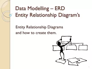
Entity Relationship Modelling. Introduction . Entity Relationship Modelling (ERM) a technique used to analyze & model the data in organizations using an Entity Relationship (E-R) diagram. Definitions. Entity set – an abstraction of similar things, e.g. cars, students

E N D
Introduction • Entity Relationship Modelling (ERM) • a technique used to analyze & model the data in organizations using an Entity Relationship (E-R) diagram.
Definitions • Entity set – an abstraction of similar things, e.g. cars, students • An entity set contains many entities • Attributes: common properties of the entities in a entity sets e.g car model, student ID • Relationship – specify the relations among entities from two or more entity sets
Background • Introduced by Peter Chen in ‘75 • now widely used • You’ll find them in: • Structured Systems Analysis and Design Methodology (SSADM) • Information Engineering (IE)
Purpose of E/R Model • provides a global quick reference to an organization’s data structures. • can be used individually to design an Information System’s (IS) data structure • can be used with Data Flow Diagrams to provide a more comprehensive IS logical design.
Purpose of E/R Model • The E/R model allows us to sketch database designs. • Kinds of data and how they connect. • Not how data changes. • Designs are pictures called entity-relationship diagrams. • Later: convert E/R designs to relational DB designs.
ERD Development Process • Identify the entities • Determine the attributes for each entity • Select the primary key for each entity • Establish the relationships between the entities • Draw an entity model • Test the relationships and the keys
A Simple Example • STUDENTs attend COURSEs that consist of many SUBJECTs. • A single SUBJECT (i.e. English) can be studied in many different COURSEs. • Each STUDENT may only attend one COURSE.
Identify the entities • Any entity can be classified in one of the following categories: • Regular : • any physical object, event, or abstract concept that we can record facts about. • Weak : • any entity that depends on another entity for its existence.
Determine the Attributes • Every Entity has attributes. • Attributes are characteristics that allow us to classify/describe an entity • e.g., entity STUDENT has the attributes: • student number • name • date of birth • course number
Key Attributes • Certain attributes identify particular facts within an entity, these are known as KEY attributes. • The different types of KEY attribute are: • Primary Key • Composite Primary Key • Foreign Key
Key Definitions • Primary Key: • One attribute whose value can uniquely identify a complete record (one row of data) within an entity. • Composite Primary Key • A primary key that consists of two or more attribute within an entity. • Foreign Key • A copy of a primary key that exists in another entity for the purpose of forming a relationship between the entities involved.
Course ER Diagram Components • Every entity diagram consists of the following components: Entity (labelled box) Relationship line Attribute
Degrees of a Relationship One-to-one (1:1) 1 1 • Woman • Man One-to-many (1:n) 1 M • Order • Customer Many-to-many (n:m) M M • Subject • Course NOTE: Every many to many relationship consists of two one to many relationships working in opposite directions
Degrees of relationship, alternative representation One-to-one (1:1) • Woman • Man One-to-many (1:n) • Order • Customer Many-to-many (n:m) • Subject • Course NOTE: Every many to many relationship consists of two one to many relationships working in opposite directions
Car Notation for optional attributes 1 M Person A person must own at least one car. A car doesn’t have to be owned by a person, but if it is, it is owned by at least one person. A person may own many cars. 1 optional relationship mandatory relationship
A Sample ER Diagram • Student • Subject • Course A Student Record Entity Diagram
Multiway Relationships • Sometimes, we need a relationship that connects more than two entity sets. • Suppose that drinkers will only drink certain beers at certain bars. • Our three binary relationships Likes, Sells, and Frequents do not allow us to make this distinction. • But a 3-way relationship would.
Example name addr name manf Bars Beers license Preferences Drinkers name addr
A Typical Relationship Set Bar Drinker Beer Joe’s Bar Ann Miller Sue’s Bar Ann Bud Sue’s Bar Ann Pete’s Ale Joe’s Bar Bob Bud Joe’s Bar Bob Miller Joe’s Bar Cal Miller Sue’s Bar Cal Bud Lite
So Far Summary In today’s session we have learned to: • Identify the entities • Determine the attributes for each entity • Select the primary key for each entity • Establish the relationships between the entities • Draw an entity model
Determine the relationship between entities name category name price makes Company Product stockprice buys employs Person name ssn address
Weak Entity Sets • An entity set that does not have a primary key is referred to as a weak entity set. • The existence of a weak entity set depends on the existence of a identifying entity set • it must relate to the identifying entity set via a total, one-to-many relationship set from the identifying to the weak entity set • Identifying relationship depicted using a double diamond • The discriminator(or partial key) of a weak entity set is the set of attributes that distinguishes among all the entities of a weak entity set. • The primary key of a weak entity set is formed by the primary key of the strong entity set on which the weak entity set is existence dependent, plus the weak entity set’s discriminator.
Weak Entity • Weak entities do not have key attributes of their own. • Weak entities cannot exist without another a relationship to another entity. • A partial key is the portion of the key that comes from the weak entity. The rest of the key comes from the other entity in the relationship. • Weak entities always have total participation as they cannot exist without the identifying relationship.
Weak Entity (cont’d) Section Section ID Identifying Relationship part of Number Course
Tips for Effective ER Diagrams 1) Make sure that each entity only appears once per diagram. 2) Name every entity, relationship, and attribute on your diagram. 3) Examine relationships between entities closely. Are they necessary? Are there any relationships missing? Eliminate any redundant relationships. Don't connect relationships to each other. 4) Use colors to highlight important portions of your diagram.
Check entity relationship diagram correctness • The following checks can be performed: • ¤ Check that each Entity Type is Normalized Experienced analysts will ensure, during analysis, that attribute types are correctly placed with entity types. However, in a project involving large numbers of analysts or inexperienced analysts, it is worthwhile to use normalization to check whether the attribute types have been assigned to the correct entity type. Normalization is also worthwhile when there have been many modifications during the analysis of interactions or checking for completeness tasks
Check entity relationship diagram correctness • ¤ Search for redundant attribute types Review the attribute types of each entity type to ensure that there is no redundancy. Read all the attribute type definitions of one entity type to search for synonyms. When you find synonyms, decide which one to remove and whether any renaming is needed. Check that the attribute type source (i.e., basic, derived, or designed) is correct. You may find that some derived attribute types are redundant (e.g., Age can be derived from Birth Date; why is Age needed if Birth Date is available?). Ensure that an algorithm exists for each derived attribute type (if the project manager has decided that all algorithms are to be defined during the BAA stage).
Check entity relationship diagram correctness • ¤ Search for overlapping entity types Review each entity type definition and check that no entity could belong to more than one entity type. If it can, there is a case for merging the two entity types or for specifying a relationship type. At the same time, review the subtypes. Are they all necessary (i.e., does each subtype have some attribute types and/or relationship types of its own?). • ¤ Search for redundant relationship types Look for "circles" of relationships on the entity relationship diagram; perhaps one of the relationships will be redundant (i.e., can one of the relationships be derived from the others?). The only way to answer this question is to think about the meaning of each relationship and to consider the cardinality and optionality of the relationships. There is no formal technique for doing this.
Check entity relationship diagram correctness • ¤ Check process/relationship type matrix If automated facilities do not exist to produce the process/attribute type matrices, this laborious subtask should be omitted.
Relationship Between ERP and DFD • DFD and ERD both are modeling techniques and have to be done for database design • DFD shows information flow and ERD shows the actual data and their relation • Both models describe the same system, they must be consistent in their use of system name • Each model can be used to help develop the other, and to check that other model is complete • In some methodologies one model can help to develop the other model e.g DFD suggest that what to include in an ERD • Mostly external Entities are use in ERD Entity set • Data store in ERD also indicate possible entities sets and you can determine their attributes • Processes also suggest relation ships