Download
1 / 19
250 likes | 816 Vues
Floating Inductors. A single Generalised Impedance Convertor (GIC) can simulate a grounded inductor. This is fine for high-pass filters. The inductors in a low-pass filter are floating…. Three Pole Example. Three pole high-pass filter. One grounded inductor and two capacitors.

E N D
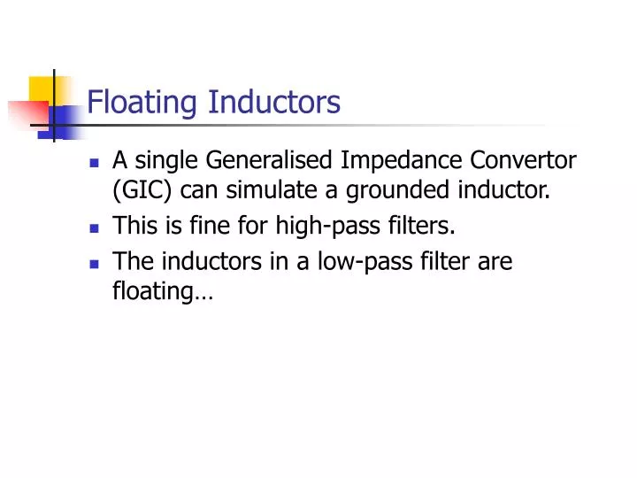
Floating Inductors • A single Generalised Impedance Convertor (GIC) can simulate a grounded inductor. • This is fine for high-pass filters. • The inductors in a low-pass filter are floating…
Three Pole Example Three pole high-pass filter. One grounded inductor and two capacitors. Three pole low-pass filter. One floating inductor and two capacitors.
Floating Inductor Properties • Current in equals current out • Impedance equals sL
Floating Inductor Replacement R GIC 1 GIC 2 sK sK
Floating Inductor Drawback • A floating inductor requires two GIC circuits, i.e. four op-amps. • An N-th order low pass filter requires N/2 floating inductors = 2N op-amps. • An N-th order high pass filter requires only N op-amps. • Solution : Frequency Dependent Negative Resistors (FDNRs)
Component Scaling • The frequency response of a passive network depends on the ratios between the impedances. • If all impedances are multiplied by the same factor, the frequency response is unchanged. • NB. Impedance of a capacitor = 1/sC (Cut-off frequency = 10 kHz)
Component Scaling II • What if all impedances are scaled by a factor of 1/s ?
Frequency Dependant Negative Resistance • Impedance is real – i.e. a resistance • It is also negative… • …and inversely proportional to the square of frequency • Hence – Frequency Dependent Negative Resistance (FDNR) • Unfortunately, it doesn’t exist…
Original passive filter 3 pole Butterworth LPF, fc = 10 kHz All impedances scaled by 1/s. All impedances scaled by 107. Low Pass Filter Design using FDNRs
Very Low Frequency Performance • Low pass filters should work all the way down to 0 Hz (d.c.) • At 0 Hz… • Theoretically, gain is still unity. • In practice, gain is undefined – dominated by the leakage resistances of the capacitors. • Solution – add a known loss resistance.
Low Frequency Stability At cut-off frequency (10 kHz) Loss resistors, r, should be much bigger (at least 50 times bigger in practice)
Practical Design • The input and output impedances are now (predominantly) capacitive. • For practical use, buffer amplifiers are required on the input and output.
Passive Filters Component Scaling Normalised Practical 0 1 0 w w 2pfC i.e. divide all inductances and capacitances by the desired cut-off frequency (in rad/s).
Passive Filters Component Scaling II Normalised Practical – High Pass 0 1 0 w w 2pfC i.e. capacitors become inductors and vice versa.
Summary • Two GICs can be used to simulate a floating inductor. • A more efficient approach scales all impedances by 1/s. • Then, the only components requiring synthesis are FDNRs. • Op-amp requirements are one-per-pole (rather than two-per-pole for floating inductor synthesis) • NB. Component simulation techniques can be used on more complex passive networks – see tutorial for example.