Download

1 / 40
400 likes | 533 Vues
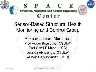
S P A C E Structures, Propulsion, And Control Engineering C e n t e r. Sensor-Based Structural Health Monitoring and Control Group. Research Team Members: Prof Helen Boussalis (CSULA) Prof Sami F Masri (USC) Jessica Alvarenga (CSULA) Armen Derkevorkian (USC). Outline.

E N D
S P A C E Structures, Propulsion, And Control Engineering C e n t e r Sensor-Based Structural Health Monitoring and Control Group Research Team Members: Prof Helen Boussalis (CSULA) Prof Sami F Masri (USC) Jessica Alvarenga (CSULA) Armen Derkevorkian (USC) NASA Grant URC NCC NNX08BA44A
Outline • Background • Objective • Theory • Modeling of 2D Beam and 3D Wing • Future Work • Timeline NASA Grant URC NCC NNX08BA44A
Background NASA Grant URC NCC NNX08BA44A
Helios Wing • Ultra-lightweight, unmanned, solar-powered flying wing aircraft • Long wingspan and high flexibility • Experienced large deformations during flight • Wing tip deflections could reach 40ft • Midair breakup at 3000ft altitude Helios Wing In-flight breakup NASA Grant URC NCC NNX08BA44A
In-flight Deformation Monitoring • Need to develop method to monitor deformations of highly flexible structures during flight • As wingtip deflections approach limitations, emergency maneuvers may be initiated • Ground-based pilots • Flight control system NASA Grant URC NCC NNX08BA44A
Existing Methods of Inflight Monitoring Electro-optical flight deflection detection • Requires onboard cameras and wing mounted targets • Heavy and requires lots of equipment Strain gages • Requires a high number of sensors in order to observe higher deflection modes of these flexible structures • The more strain sensing stations are used, the heavier the load on the wing • Too heavy and impractical for most weight conscious aircraft NASA Grant URC NCC NNX08BA44A
Newly Proposed Method • Fiber Optic Sensors with Fiber-Bragg Gratings • Immune to E&M/RF interference and radiation • Light weight and small (thin fibers) • Ability to multiplex 100’s of sensors onto a single fiber • Potential for embedment into structures Reflector Laser Light Loss Light Reflected Light (IR) NASA Grant URC NCC NNX08BA44A
Application • Validation of fiber optic sensor measurements and real-time wing shape sensing on NASA’s Ikhana Vehicle NASA Grant URC NCC NNX08BA44A
In-Flight Shape Detection Algorithms • Deflection Shape Algorithms based on strain data • Validation with classical beam theory, and finite element analysis (FEA) • Promising results, with much room for improvement NASA Grant URC NCC NNX08BA44A
Structural Health Monitoring (SHM) • Objectives • System Identification • Damage Detection • Broad applications in civil, mechanical, and aerospace industries • Special importance after natural disasters (earthquakes), during key flying missions (Helios) NASA Grant URC NCC NNX08BA44A
Structural Health Monitoring (SHM) • Destructive Evaluation (DE) • Physical Decomposition to locate damage • Non-Destructive Evaluation (NDE) • Based on vibration signatures (Acc, Vel, Dsp) • Enables real-time monitoring • Involves sophisticated algorithms NASA Grant URC NCC NNX08BA44A
Non-Destructive Evaluation (NDE) • Parametric Techniques • Involves major assumptions about the model • Prior knowledge about the parameters • Advantages • Well-Developed techniques, such as least-square, Kalman Filter, Eigen Value Realization Algorithm (ERA) along with the Natural Excitation Technique (NExT), among others. • Track certain parameters in great detail which allows detecting changes “damages” NASA Grant URC NCC NNX08BA44A
Non-Destructive Evaluation (NDE) • Non-Parametric Techniques • No knowledge about the model is required • “Black-Box” or “Unknown-Structures” approach • Applicability on linear and non-linear systems • Well-developed algorithms such the neural networks NASA Grant URC NCC NNX08BA44A
Objective NASA Grant URC NCC NNX08BA44A
Vision • Objectives: Develop and implement innovative methods for utilizing fiber-optic strain sensors for structural health monitoring and control applications in aerospace systems, with emphasis on using on-line aeroelastic shape estimation methods under realistic flight conditions. • Approach: Conduct analytical and experimental studies on a subset of challenging research issues to develop and evaluate a variety of modeling, monitoring and control strategies. • Applicability: Results of the research will be useful in the monitoring and control of a wide variety of current as well as future generations of aircraft and aerospace structures. NASA Grant URC NCC NNX08BA44A
Preliminary Tasks Task 1: Development and validation of a NASTRAN model for a 2D beam and a 3D wing Task 2: Computational studies with NASTRAN model for shape determination from strain measurements under deterministic excitation Task 3: Computational studies with NASTRAN model for shape determination from strain measurements under stochastic aerodynamic loads Task 4: Damage detection studies based on NASTRAN model to assess sensitivity of strain measurements to damage type, severity, location, and orientation, under uncertain conditions NASA Grant URC NCC NNX08BA44A
In-flight deformation shape sensing theory NASA Grant URC NCC NNX08BA44A
Development of Deflection Equations NASA Grant URC NCC NNX08BA44A
Classical Beam Theory • Classical Beam Differential Equation: M(x): bending moment E: Young modulus I: moment of inertia • By relating the bending moment to the associated bending strain at the top or bottom fiber: σ(x): bending stress c: half-beam depth NASA Grant URC NCC NNX08BA44A
Cantilever Tubular Spar Δl : spacing between sensing stations c: half-beam depth γi: torsion strain sensing station xi: strain sensing station M: bending moment ε: bending strain θ: slope angle y: deflection NASA Grant URC NCC NNX08BA44A
Bending: Slope Equations • Slope Equation from Classical Beam Theory: • Noting that at the built-in end, tan θ0=0, gives: • Final Equation θi+1 θi θi-1 NASA Grant URC NCC NNX08BA44A
Bending:Deflection Equations • Deflection equation from slope equation: • Noting that at the built-in end, y0=tan θ 0=0. • Final Equation θi+1 yi+1 θi yi yi-1 θi-1 NASA Grant URC NCC NNX08BA44A
2D Beam NASA Grant URC NCC NNX08BA44A
FEMAP Model 2D Beam Element • 55 Nodes • 40 Elements • Aluminum • 0.1 unit thickness • 10 units in length • 2unit deep • Deterministic point load = 60 pounds • Beam fixed in all 6 degree of freedom at root • Deformation shows wing deflection • Contour shows bending-strain measurements NASA Grant URC NCC NNX08BA44A
Calculation of Strain • Case 1: Strain sensing station located in the middle of an element • Case 2: Strain sensing station located at the juncture of two elements xi e xi Deformation of an infinitesimal rectangular material element [Sanpaz 2008] i- i+ e e δi: represents the displacement measurements e: represents the finite-element span-wise length xi:the i-th sensing station NASA Grant URC NCC NNX08BA44A
2D Beam Results NASA Grant URC NCC NNX08BA44A
2D Beam Results NASA Grant URC NCC NNX08BA44A
2D Beam Results • Calculation of error: e: error a: reference measurement (FEA) ã:analyzed measurement (Case1 and 2) || . ||: norm NASA Grant URC NCC NNX08BA44A
3D Wing NASA Grant URC NCC NNX08BA44A
FEMAP Wing Model • 138 Nodes • 284 Elements • 6 deterministic point loads each 250 lbs • Pressure distribution along upper and lower wing skins • Varying half-beam depth and width along span NASA Grant URC NCC NNX08BA44A
3D Wing Details NASA Grant URC NCC NNX08BA44A
3D Wing Details NASA Grant URC NCC NNX08BA44A
Potential Placement of Fiber Sensors NASA Grant URC NCC NNX08BA44A
Wing Deflection Contour shows deflection values in y-direction NASA Grant URC NCC NNX08BA44A
Future Work NASA Grant URC NCC NNX08BA44A
Future Tasks • Validation of: • Combined Bending and Torsion (CBT) Theory • Perturbation Method • Stepwise Method • Modeling artificial damage in 3D model • Error analysis and classification NASA Grant URC NCC NNX08BA44A
Timeline NASA Grant URC NCC NNX08BA44A
Timeline NASA Grant URC NCC NNX08BA44A
References Emmons, M., Karnani, S., Trono, S., Mohanchandra, K., Richards, W., and Carman, G. 2010. Strain Measurement Validation Of Embedded Fiber Bragg Gratings. International Journal of Optomechatronics, 4(1):22-33. Ko, W. and Richards, W. 2009. Method for real-time structure shape-sensing. Ko, W., Richards, W., and Tran, V. 2007. Displacement Theories for In-Flight Deformed Shape Predictions of Aerospace Structures. Sanpaz. 2008. Deformation of an infinitesimal rectangular material element. Wikepedia, Accessed January 27, 2011. http://en.wikipedia.org/wiki/File:2D_geometric_strain.png NASA Grant URC NCC NNX08BA44A
Questions? Thank You NASA Grant URC NCC NNX08BA44A