Download
1 / 26
260 likes | 441 Vues
Dec. 6 th , 2011. Multi-scale Heat Conduction Solution of the EPRT. Hong goo, Kim 1 st year of M.S. course. Contents. Introduction Two-Flux Method Modeling of Thin Layer Solution Example 7-4 Thermal Resistance Network Method Scheme Thermal Resistance Network

E N D
Dec. 6th , 2011 Multi-scale Heat ConductionSolution of the EPRT Hong goo, Kim 1st year of M.S. course
Contents • Introduction • Two-Flux Method • Modeling of Thin Layer • Solution • Example 7-4 • Thermal Resistance Network Method • Scheme • Thermal Resistance Network • Three-Layer Structure
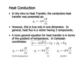
Two-Flux Method Modeling of Thin Layer • Assumption Scheme • 1-D, Steady state • Medium is gray Emission • Absorption coefficient is independent of phonon frequency T1 T2 • Walls are diffuse and gray ε1 ε2 • Absorption coefficient is independent of direction and phonon frequency • Emission at wall is independent of direction • Governing Equation Steady-state EPRT Gray medium ; Positive direction ; Negative direction x = L x = 0
Two-Flux Method • Modeling of Thin Layer • Boundary Conditions • Temperature at the walls (7.46) • Intensity at the walls (7.47) Emission Emission (7.48) Reflection Reflection T1 T2 Irradiation Irradiation x = L x = 0
Two-Flux Method • Solution • Derivation of the Solutions • From the governing equation (EPRT) (7.45a) • Integrating from 0 to x, after multiplying on both sides LHS RHS LHS RHS
Two-Flux Method • Solution • Derivation of the Solutions (continued) • For positive directions (from left to right) (7.49) (7.50) Attenuation of the intensity originated from the left surface (x = 0) Generation term • For negative directions (from right to left)
Two-Flux Method • Solution • Spectral Net Heat Flux (in x-direction) (7.37) Appendix (1) (7.51a) • For a diffuse surface (x = 0, x = L) Diffuse Surface (7.51b)
Two-Flux Method • Solution • Energy Balance • For 1-D steady-state, • Differentiation of heat flux (diffuse surface) from (7.51b) Appendix (2) (7.52)
Two-Flux Method • Solution • Energy Balance • Total blackbody emissive power = total radiosities at 1 and 2 • Blackbody emissive power • Total radiosity • Energy balance, from (7.52) → Radiative equilibrium condition
Two-Flux Method • Example 7-4 • Objectives • Heat flux • Thermal conductivity • Temperature distribution • Assumptions • Medium is gray • Surfaces are diffuse and gray • Radiative thicklimit : Kn =Λ/L<< 1
Two-Flux Method • Example 7-4 • Spectral Heat Flux • In the radiative thick limit : Λ << x, Λ << L − x • Local equilibrium holds if location of x is not too close to either surfaces • Flux originating from the left/right surfaces are attenuated to ‘0’ (7.51a)
Two-Flux Method • Example 7-4 • Spectral Heat Flux (continued) • Exponential terms are significant only in the neighbor of x • Taylor series 1st order approximation is valid (7.54)
Two-Flux Method • Example 7-4 • T << θD • Net heat flux obtained from integrating (7.54) over frequency • Thermal conductivity Thermal conductivity (7.55a) • From kinetic theory • Integration of (7.55a) overx from 0 to L : (7.55b) LHS RHS (7.56a) Net heat flux
Two-Flux Method • Example 7-4 • T << θD(continued) • Temperature distribution • By comparing (7.55a) and (7.56a) (7.56b) • Thermal resistance • By definition of the thermal resistance and (7.56a) (7.57)
Two-Flux Method • Example 7-4 • T > θD • Spectral heat flux (7.54) (7.34) • Total intensity • Net heat flux (7.58)
Two-Flux Method • Example 7-4 • T > θD • Thermal conductivity • Net heat flux • From kinetic theory, (7.58) (7.59) • Assuming small temperature difference • Thermal conductivity can be approximated as a constant • Thermal resistance • Temperature distribution
Two-Flux Method • Example 7-4 • Temperature Profiles • T • (T > θD) • (T << θD) • x
Two-Flux Method • Example 7-4 • Radiative Equilibrium Conditions • Local equilibrium condition, gray medium (7.40) • is the average of and • Assuming T1 > T2: net heat flux in positive x • should be greater than • Local equilibrium is not a stable state • Heat flux in the radiative thin limit (7.60)
Thermal Resistance Network • Scheme • Internal Thermal Resistance • Diffusion process: classical Fourier law • Boundary Thermal Resistance • When medium is not in radiative thick limit • Due to radiation slip • Does not exist in classical Fourier law • Temperature jump approaches to zero in the radiative thick limit ( Kn << 1 ) • Restrictions • Applicable to one-dimensional problem • Results in temperature jump at the boundaries
Thermal Resistance Network • Energy Transport • T << θD • Heat flux in thermal network resistance (7.61) Bulk Radiation slip • For blackbody walls ( ε1 = ε2= 1 ) • Temperature difference between T1 and T2 is small (T1, T2≈ T ) Effective thermal conductivity (7.63) Bulk thermal conductivity (7.55b)
Thermal Resistance Network • Energy Transport • T > θD • Heat flux in thermal network resistance (7.64) • Effective vs. bulk heat conductivity ratio is the same as in low temperature for blackbody walls • Discussion • Fourier law can be applied inside the medium • Heat flux for thermal resistance network can be applied between the diffusion and ballistic extremes
Thermal Resistance Network • Three Layer Structure • Thermal Resistance Network TH TL TH T1a T1b T2a T2b T3a T3b TL
Thermal Resistance Network • Three Layer Structure • Internal Resistance • Due to diffusion (Fourier’s law) • Interface Resistance • Transmission of phonon through the interface Γij : transmissivity from ito j • Boundary Resistance • Transmission of phonon transport considered
Thermal Resistance Network • Three Layer Structure • Total Resistance • Heat Flux • Effective Thermal Conductivity