Download
1 / 22
450 likes | 1.26k Vues
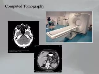
Computed Tomography. Kalpana Kanal, Ph.D., DABR Assistant Professor, Diagnostic Physics Dept. of Radiology UW Medicine a copy of this lecture may be found at: http://courses.washington.edu/radxphys/PhysicsCourse.html. System Geometry. c.f. RSNA/AAPM web module: CT Systems. 128- slice

E N D
Computed Tomography Kalpana Kanal, Ph.D., DABR Assistant Professor, Diagnostic Physics Dept. of Radiology UW Medicine a copy of this lecture may be found at: http://courses.washington.edu/radxphys/PhysicsCourse.html
System Geometry c.f. RSNA/AAPM web module: CT Systems Kanal
128- slice 256-slice 320- slice 2007-2008 Kanal
Fast Scanning, 0.3 sec Kanal
Helical/Spiral CT • Patient is transported continuously through gantry while data are acquired continuously during several 360-deg rotations c.f. Kalender WA, et.al. Radiology, 176(1):181-3, 1990 Kanal
Table increment per rotation (mm) Pitch = Beam collimation (mm) Helical CT - Pitch • Pitch is a parameter than comes to play when helical scan protocols are used • Typical Pitch Ratio - 0.5, 1.0, 1.375, 1.5, 2.0 • Pitch = 1, same as contiguous axial scanning • Pitch <1 implies overlapping and higher patient dose • Slight improvement in image quality • Pitch >1 implies extended imaging and reduced patient dose • Partial scanning, faster scan time, less patient motion, maybe smaller volume of contrast used Kanal
SDCT versus MDCT *Rydberg et. al., Radiographics 2000, 20:1787 Kanal
Single Slice vs. Multislice (Multidetector) CT c.f. Seeram. Computed Tomography, 2nd ed., p. 258. c.f. RSNA/AAPM web module: CT Systems Kanal
Slice Width Selection GE 64 MDCT (40 mm detector) 64 x 0.625 mm 32 x 1.25 mm 16 x 2.5 mm 8 x 5 mm c.f. http://www.impactscan.org/slides/impactcourse/helical_and_multi-slice_principles/img17.html Kanal
MSCT - Advantages • MSCT speed can be used for fast imaging for larger volumes of tissue with wide sections • Same acquisition in shorter times (fewer motion artifacts) • Thinner slices for better z-axis resolution • Efficient use of x-ray beam, reduction of radiation dose (?) • Reconstruction in different slice widths • Possibility of Isotropic Imaging (better MPRs and 3D images with reduced image artifacts) Kanal c.f. Seeram. Computed Tomography, 2nd ed., p. 263.
Radiation Dose in CTWhy is it important? Kanal c.f. RSNA/AAPM web module: Radiation dose in CT
New York Times July 31, 2010 Kanal
CT Dose Descriptors • CTDIvol is the approximate average radiation dose over x, y, and z axis of the patient Kanal cf: Morin RL, et al, Circulation 2003;107:917-22
CT Dose Descriptors • The Dose Length Product is an indicator of the integrated radiation dose of an entire CT examination • It incorporates the number of scans and the scan width Kanal cf: Morin RL, et al, Circulation 2003;107:917-22
CT Dose Descriptors Morin RL, et al, Circulation 2003;107:917-22 • A reasonable approximation of E can be obtained by multiplying DLP with a conversion factor, k●which varies dependent on body part imaged and age of patient E = k * DLP Kanal ● k factors available in AAPM report 96, 2008
Average Effective Dose (mSv) for CT Procedures Kanal cf: Mettler et al. Radiology 2008, 248(1):254-263
Factors that influence dose – Patient Size • Dose increases with increase in kilovoltage (kVp) and mAs (tube current * rotation time) • Patient size – dose more for smaller patients • Reduce technique factors when scanning smaller adults and pediatric patients • Organ Dose • Head CT • Thyroid - 1.9 mGy • Eye lens - 40 mGy • Chest CT • Breast - 21 mGy Kanal
Abdomen CT Uterus – 8 mGy Gonads - 8 mGy Pelvis CT Uterus – 26 mGy Gonads - 23 mGy Patient skin doses are typically between 20 (body) and 40 mGy (head) or 2 to 4 rad Induction of erythema is typically 2 Gy Organ Doses in CT Kanal
Current Modulation or AEC in CT • Modern CT scanners are capable of modulating the mA (current) during the scan • The rationale behind this technique is that it takes fewer photons (lower mA) to penetrate thinner tissue, and more x-ray photons (higher mA) are needed to penetrate thicker projections through the body • Dose can be reduced • MHRA Report 05016: CT scanner automatic exposure control systems, February 2005, UK Kanal
Current Modulation or AEC in CT • Aim of an AEC system in CT is to significantly reduce, or eliminate variations in image quality between different images • Which in turn reduces the variation in radiation dose to different sized patients • In current systems, this is accomplished by controlling the x-ray tube current to acquire the specified level of image noise • Three levels of AEC: patient size AEC, z-axis AEC, rotational AEC • MHRA Report 05016: CT scanner automatic exposure control systems, February 2005, UK Kanal