Download

1 / 33
450 likes | 1.09k Vues
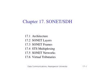
SDH. SDH / SONET. Introduction to SDH/ SONET Applications / advantages/ disadvantages Physical Configuration SONET/ SDH Layers Transmission Formats and Speed Optical Interfaces Specifications SONET/ SDH Rings SONET/SDH Networks. Introduction to SDH / SONET.

E N D
SDH / SONET • Introduction to SDH/ SONET • Applications / advantages/ disadvantages • Physical Configuration • SONET/ SDH Layers • Transmission Formats and Speed • Optical Interfaces Specifications • SONET/ SDH Rings • SONET/SDH Networks
Introduction to SDH / SONET ITU-T standards is called the Synchronous Digital Hierarchy (SDH) ANSI standards is called the Synchronous Optical Network (SONET) • Three Important concerns in designing SONET/ SDH* • It is a Synchronous network. • A single clock is used to handle the timing of transmission and equipment across the entire network. • Network wise synchronization adds a level of predictability to the system. • This predictability , coupled with powerful frame design, enables individual channels to be multiplexed, thereby improving speed and reducing cost. • Standardization. • SDH/SONET contains recommendations for the standardization of fiber optic transmission system equipment sold by different manufacturers.
Introduction to SDH / SONET • 3.Universal Connectivity. • SDH/SONET physical specification and frame design include mechanism that allow it to carry signals from incompatible tributary systems. This flexibility gives SONET/ SDH a reputation for universal connectivity. • Applications: • Carrier for ISDN and B-ISDN. • Carrier for ATM cells. • Can support bandwidth on demand. • Can be used as the backbone or totally replace other networking protocols such as SMDS or FDDI. • Can replace PDH system,E1, E3 lines.
Flexible New generation of multiplexers with direct access to every single low-speed tributary (e.g. 2 Mbit/s/1.5 Mbit/s), sophisticated signal protection mechanisms Cost effective Integration of multiplex, cross-connect andline terminal functions as part of a software-controlled network element Manageable Adequate and standardized signal overhead capacity for remote operation, administration and maintenance (OAM) Standardized Standardized line signal as a uniform interface for all manufacturers (multi-vendor policy) International Uniform multiplexing principle for both existing hierarchies (USA and Europe) Introduction to SDH / SONET Advantages of SDH
Disdvantages of SDH Abundant Overheads bits low bandwidth utilization ratio, contradiction between efficiency and reliability Mechanism of pointer adjustment is complex, it can cause pointer adjustment jitters Pointer adjustment Large-scale application of software makes SDH system vulnerable to viruses or mistakes. Software based
Physical Configuration* Add/drop multiplexer Regenerator Regenerator MUX MUX Section Section Section Section Line Line Path
Multiplexer/ Demultiplexer: Multiplexer marks the beginning and end points of a SDH link. They provide interface between a tributary network and SDH and either multiplex signals from multiple sources into an STM signal or demultiplex as STM signal into different destination Signals. Regenerator:Regenerator extend the length of the links, it takes optical signal and regenerates. SDH regenerator replaces some of the existing overhead information with new information. These devices function at the data link layer. Add/ drop multiplexer:It can add signals coming from different sources into a given path or remove a desired signal from a path and redirect it without demultiplexing the entire signal. Instead of relying on timing and bit position add/drop multiplexer use header information such as addresses and pointers to identify the individual steams.
Section:It is the optical link connecting two neighbor devices: • Multiplexer to Multiplexer • Multiplexer to Regenerator • Regenerator to Regenerator • Line:It is the portion of the network between two multiplexers: • STM Multiplexer to add/drop multiplexer • Two add/drop multiplexers • Two STM multiplexers Paths:It is the end to end portion of the network between two STM multiplexers. In a simple SDH of two multiplexers linked directly to each other, the section, line, and path are the same.
SONET/SDH Layers Path layer Line layer Section layer Data link Photonic layer Physical
SONET/SDH Layers Photonic Layer:Corresponds to the physical layer of the OSI model. It includes physical specifications for the optical fiber channel, the sensitivity of the receiver, multiplexing functions, and so on. It uses NRZ encoding. Section Layer:It is responsible for the movement of a signal across a physical section. It handles framing, scrambling and error control. Section layer overhead is added to the frame at this layer. Line Layer:It is responsible for the movement of a signal across a physical line. Line overhead (Pointers, protection bytes, parity bytes etc) is added to the frame at this layers. STM multiplexer and add/drop multiplexers provide line layer functions. Path Layer:It is responsible for the movement of a signal from its optical source to its optical destination. At the optical source, the signal is changed from an electronic form into an optical form, multiplexed with other signals, and encapsulated in a frame. Path layer overhead is added at this layer. STM multiplexer provide path layer functions.
Device Layer Relationship Path Path Line Line Line Section Section Section Section Section Photonic Photonic Photonic Photonic Photonic Regenerator Regenerator MUX MUX Add/drop multiplexer
Transmission Formats and speeds Commonly Used SONET and SDH Transmission Rates QUIZ: No of E1s in STM-1,STM-4,STM-16 and STM-64 ?
9 270 Transmission Formats and speeds Line rate calculation Total Frame Capacity: 270 X 9 = 2430 Bytes Total Number of Bits = 2430 X 8 = 19440 Bits Time Period of One Frame = 125 microseconds Bits/Second = 19440/125 X 10 -6 = 155.52 Mbits/Sec = STM-1 4X STM-1 = STM-4 4XSTM-4 = STM-16
Transmission Formats and seeds SDH components • SDH Frame is made of the following • SDH payload • Pointer • Path Over head • Section Overhead • Multiplex section overhead • Regenerator section overhead Overhead is fixed and is like a Header. It contains all information including Monitoring,O&M functions etc.
Transmission Formats and speeds SDH Frame 2 34 140 SDH 270 x N Columns 1 Byte 261 Bytes RSOH Pointer 9 Rows Payload POH MSOH Actual Traffic STM-1, STM-4, STM-16, STM-64, STM-256
SONET/ SDH Rings • SONET and SDH are configured as either ring or mesh architecture. • So Loop diversity is achieved in case of link or equipment failure. • SONET/SDH rings are commonly called self-healing rings. Means automatic switching to standby link on failure or degradation of the link. • Three main features of SONET/SDH rings: • There can be either two or four fibers running between the nodes on a ring. • Operating signal signals can travel either clockwise only (unidirectional ring) or in both directions around the ring (which is called bidirectional ring). • Protection switching can be performed either via line-switching or a path switching scheme. • Line switching moves all signal channels of an entire STM-N channel to a protection fiber. • Path switching can move individual payload channels within a STM-N channel to another path.
SONET/ SDH Rings • Following two architectures have become popular for SONET and SDH Networks: • Two fibers, unidirectional, path-switched ring (two-fiber UPSR) • Two fiber or four fiber, bidirectional, line switched ring( two fiber or four fiber BLSR)\ • (They are also referred to as unidirectional or • bidirectional self healing ring , USHRs or BSHRs)
SONET/ SDH Rings Flow of primary and protection traffic from node 1 to node 3 Generic two fiber unidirectional path-switched ring (UPSR) with counter rotating protection path.
SONET/ SDH Rings Architecture of a four-fiber bidirectional line-switched ring (BLSR).
SONET/ SDH Rings Reconfiguration of a four-fiber BLSR under transceiver or line failure.
SONET /SDH Networks • SONET/SDH equipment allows the configuration of a variety of network architectures, as shown in next slide. For example • Point-to-point links • Linear chains • UPSRs • BLSRs • Interconnected rings Each of the individual rings has its own failure recovery mechanisms and SONET/SDH network management procedures. An important SONET/SDH network element is the add/drop multiplexer (ADM). This piece of equipment is a fully synchronous, byte-oriented multiplexer that is used to add and drop subchannels within an OC-N signal. The SONET/SDH architectures also can be implemented with multiple wavelengths. For example, Fig in next slide, will show a dense WDM deployment on an OC-192 trunk ring for n wavelengths
SONET /SDH Networks Where OC-3 = STM-1 OC-12 = STM-4 OC-48 = STM-16 OC-192= STM-64 Generic configuration of a large SONET network consisting of linear chains and various types of interconnected rings.
SONET /SDH Networks Functional concept of an add/drop multiplexer for SONET/SDH applications.
SONET /SDH Networks Dense WDM deployment of n wavelengths in an OC-192/ STM-64 trunk ring.
Mapping • Is the procedure through which signals are packed inside an SDH frame • PDH signal passes through the following steps before emerging as an SDH Signal • Container (C-X) • Virtual Container (VC-X) • Tributary Unit (TU-X) • Tributary Unit Group (TUG-X) • Administrative Unit (AU-4) • STM Signal
How 2 Mb signals are mappedinto an SDH stream? Container C-12 2 Mb/Sec Path Overhead (POH) Virtual Container VC-12
9 270 How 2 Mb signals are mappedinto an SDH stream? VC-12 Starting address of Payload in VC. Payload Pointer TU (Tributary Unit) SOH STM-1/4/16 SOH
Formation of Synchronous Signal Plesiochronous signal Container (C) Path overhead Additional information forend-to-end monitoring Virtual container (VC) Pointer Phase relation between virtual container (payload) and subordinate frame Tributary unit (TU) Synchronous Signal
ITU-T recommendation G.707 and its realization STM-N × n × 1 AUG C4 AU4 VC4 140 Mbit/s × 1 × 3 TUG3 TU3 VC3 34 Mbit/s C3 VC3 AU3 (45 Mbit/s) × 7 AU/G Administrative unit/group C Container STM Synchronous transport module TU/G Tributary unit/group VC Virtual container Pointer processing Multiplexing Aligning Mapping Cross-connect level × 1 VC2 C2 TUG2 TU2 (6 Mbit/s) × 3 C12 TU12 2 Mbit/s VC12 VC11 C11 TU11 (1.5 Mbit/s) Source: TR BM TP 5
SDH Overheads • An overhead is like a delivery notice with the parcel which contains information about the contents, Condition, type, address, postal date, weight etc. of the parcel. • In the SDH a distinction is made between Section Overhead (SOH) and Path Overhead (POH) STM-1 SOH SOH POH VC-4
SDH Multiplexing Structure ×1 Mapping AUG-64 STM-64 Aligning ×4 Multiplexing ×1 AUG-16 STM-16 Pointer processing ×4 ×1 AUG-4 STM-4 ×4 ×1 ×1 AU-4 VC-4 C-4 AUG-1 STM-1 139264 kbit/s ×3 TU-3 VC-3 C-3 ×1 TUG-3 34368 kbit/s ×7 TUG-2 TU-12 VC-12 C-12 2048 kbit/s ×3