Download
1 / 83
870 likes | 1.26k Vues
Video Coding Concept. By: Eng. Mohanned Dawoud. video coding. Video coding is the process of compressing and decompressing a digital video signal. Video Sequence and Picture. Video sequence Large amount of temporal redundancy

E N D
Video Coding Concept By: Eng. Mohanned Dawoud
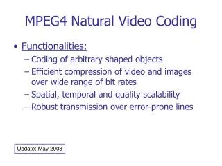
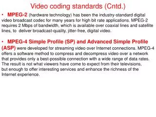
video coding • Video coding is the process of compressing and decompressing a digital video signal.
Video Sequence and Picture • Video sequence • Large amount of temporal redundancy • Video compression (video coding) is the process of compacting or condensing a digital video sequence into a smaller number of bits. • ‘Raw’ or uncompressed digital video typically requires a large bitrate. • Compression is necessary for practical storage and transmission of digital video. Intra 0 Inter 1 Inter 2 Inter 3 Inter 4 Inter 5
Video Coding Concepts • Compression involves a complementary pair of systems, a compressor (encoder) and a decompressor (decoder). • The encoder converts the source data into a compressed form (occupying a reduced number of bits) prior to transmission or storage • the decoder converts the compressed form back into a representation of the original video data. • The encoder/decoder pair is often described as a CODEC (enCOder/ DECoder) .
Capture • Representing a visual scene in digital form involves sampling the real scene: • Spatially: usually on a rectangular grid in the video image plane. • Temporally as a series of still frames or components of frames sampled at regular intervals in time.
Video Coding Concepts • Most video coding methods exploit both temporal and spatial redundancy to achieve compression.
Video Coding Concepts • In the temporal domain, there is usually a high correlation (similarity) between frames of video that were captured at around the same time. • Temporally adjacent frames (successive frames in time order) are often highly correlated, especially if the temporal sampling rate (the frame rate) is high. • In the spatial domain, there is usually a high correlation between pixels (samples) that are close to each other, i.e. the values of neighboring samples are often very similar.
Spatial Sampling • Sampling the signal at a point in time produces a sampled image or frame that has defined values at a set of sampling points. • The most common format for a sampled image is a rectangle with the sampling points positioned on a square or rectangular grid.
Temporal Sampling • A moving video image is captured by taking a rectangular ‘snapshot’ of the signal at periodic time intervals. • Playing back the series of frames produces the appearance of motion. • A higher temporal sampling rate (frame rate) gives apparently smoother motion in the video scene but requires more samples to be captured and stored.
Temporal Sampling • Frame rates below 10 frames per second are sometimes used for very low bit-rate video communications (because the amount of data is relatively small). • Between 10 and 20 frames per second is more typical for low bit-rate video communications; the image is smoother but jerky motion may be visible in fast-moving parts of the sequence.
Temporal Sampling • Sampling at 25 or 30 complete frames per second is standard for television pictures. • 50 or 60 frames per second produces smooth apparent motion (at the expense of a very high data rate).
Frames and Fields • A video signal may be sampled as a series of complete frames (progressive sampling) or as a sequence of interlaced fields (interlaced sampling). • In an interlaced video sequence, half of the data in a frame (one field) is sampled at each temporal sampling interval. • A field consists of either the odd-numbered or even-numbered lines within a complete video frame. • An interlaced video sequence contains a series of fields, each representing half of the information in a complete video.
Frames and Fields • The advantage of interlaced sampling method is that it is possible to send twice as many fields per second as the number of frames in an equivalent progressive sequence with the same data rate, giving the appearance of smoother motion. • For example, a video sequence consists of 50 fields per second and, when played back using interlaced sampling, motion can appears smoother than in an equivalent progressive video sequence containing 25 frames per second.
VIDEO CODEC • A video CODEC encodes a source image or video sequence into a compressed form and decodes this to produce a copy or approximation of the source sequence. • CODEC represents the original video sequence by a model. • Model: (an efficient coded representation that can be used to reconstruct an approximation of the video data).
VIDEO CODEC • Ideally, the model should represent the sequence using as few bits as possible and with as high a fidelity as possible. • These two goals (compression efficiency and high quality) are usually conflicting. • lower compressed bit rate typically produces reduced image quality at the decoder.
VIDEO CODEC • A video encoder consists of three main functional units: • A temporal model. • A spatial model. • An entropy encoder.
VIDEO CODEC • The input to the temporal model is an uncompressed video sequence. • The temporal model attempts to reduce temporal redundancy by exploiting the similarities between neighboring video frames (usually by constructing a prediction of the current video frame).
VIDEO CODEC • In MPEG-4 Visual and H.264, the prediction is formed from one or more previous or future frames. • Then it is improved by compensating for differences between the frames (motion compensated prediction).
VIDEO CODEC • The output of the temporal model is: • Residual frame (created by subtracting the prediction from the actual current frame). • A set of model parameters, typically a set of motion vectors describing how the motion was compensated.
VIDEO CODEC • The residual frame forms the input to the spatial model. • Spatial model makes use of similarities between neighboring samples in the residual frame to reduce spatial redundancy.
VIDEO CODEC • In MPEG-4 Visual and H.264 the spatial model is achieved by applying a transform to the residual samples and quantizing the results. • The transform converts the samples into another domain in which they are represented by transform coefficients. • The coefficients are quantized to remove insignificant values, leaving a small number of significant coefficients that provide a more compact representation of the residual frame.
VIDEO CODEC • The output of the spatial model is a set of quantized transform coefficients.
VIDEO CODEC • The parameters of the temporal model (typically motion vectors) and the spatial model (coefficients) are compressed by the entropy encoder. • This removes statistical redundancy in the data (for example, representing commonly-occurring vectors and coefficients by short binary codes) and produces a compressed bit stream or file that may be transmitted and/or stored.
VIDEO CODEC • A compressed sequence consists of: • Coded motion vector parameters. • Coded residual coefficients. • Header information.
VIDEO CODEC • The video decoder reconstructs a video frame from the compressed bit stream. • The coefficients and motion vectors are decoded by entropy decoder. • After decoding, the spatialmodel is decoded to reconstruct a version of the residual frame. • The decoder uses the motion vector parameters, together with one or more previously decoded frames, to create a prediction of the current frame. • The frame itself is reconstructed by adding the residual frame to this prediction.
TEMPORAL MODEL • The goal of the temporal model is to reduce redundancy between transmitted frames by forming a predicted frame and subtracting this from the current frame. • The output of this process is a residual (difference) frame. • The more accurate the prediction process, the less energy is contained in the residual frame. • The predicted frame is created from one or more past or future frames (‘reference frames’).
Prediction from the Previous Video Frame • The simplest method of temporal prediction is to use the previous frame as the predictor for the current frame. • In this image, mid-grey represents a difference of zero and light or dark greys correspond to positive and negative differences respectively.
Prediction from the Previous Video Frame • The obvious problem with this simple prediction is that a lot of energy remains in the residual frame (indicated by the light and dark areas). • This means that there is still a significant amount of information to compress after temporal prediction. • Much of the residual energy is due to object movements between the two frames and a better prediction may be formed by compensating for motion between the two frames.
Changes due to Motion • Changes between video frames may be caused by: • Object motion (rigid object motion, for example a moving car, and deformable object motion, for example a moving arm). • Camera motion (panning, tilt, zoom, rotation). • Uncovered regions (for example, a portion of the scene background uncovered by a moving object). • lighting changes.
Changes due to Motion • With the exception of uncovered regions and lighting changes, these differences correspond to pixel movements between frames. • It is possible to estimate the trajectory of each pixel between successive video frames, producing a field of pixel trajectories known as the optical flow.
Block-based Motion Estimation and Compensation • A practical and widely-used method of motion compensation is to compensate for movement of rectangular sections or ‘blocks’ of the current frame. • The procedure is carried out for each block of M × N samples in the current frame.
Block-based Motion Estimation and Compensation • Search an area in the reference frame (past or future frame, previously coded and transmitted) to find a ‘matching’ M × N-sample region. • Find the region that gives the ‘best’ match. • This process of finding the best match is known as motion estimation. • The chosen candidate region becomes the predictor for the current M × N block. • It is subtracted from the current block to form a residual M × N block (motion compensation). • The residual block is encoded and transmitted and the offset between the current block and the position of the candidate region (motion vector) is also transmitted.
Block-based Motion Estimation and Compensation • The decoder uses the received motion vector to re-create the predictor region. • Then decodes the residual block. • Adds the residual block to the predictor and reconstructs a version of the original block.
Block-based Motion Estimation and Compensation • Block-based motion compensation is popular for a number of reasons: • It is relatively straightforward and computationally tractable. • It provides a reasonably effective temporal model for many video sequences.
Block-based Motion Estimation and Compensation • There are however a number of disadvantages: • ‘Real’ objects rarely have neat edges that match rectangular boundaries. • Objects often move by a fractional number of pixel positions between frames and many types of object motion are hard to compensate for using block-based method(e.g. deformable objects, rotation and warping, complex motion such as a cloud of smoke). • Despite these disadvantages, block-based motion compensation is the basis of the temporal model used by all current video coding standards.
Motion Compensation Block Size Frame 1 Frame 2
Motion Compensation Block Size Residual (no motion compensation) Residual (16 × 16 block size)
Motion Compensation Block Size Residual (8 × 8 block size) Residual (4 × 4 block size)
Motion Compensation Block Size • Smaller motion compensation block sizes can produce better motion compensation results. • However, a smaller block size leads to: • Increase in complexity (more search operations must be carried out) • Increase in the number of motion vectors that need to be transmitted.
IMAGE MODEL (spatial model) • A natural video image consists of a grid of sample values. • Natural images are often difficult to compress in their original form because of the high correlation between neighbouring image samples. • Efficient motion compensation reduces local correlation in the residual making it easier to compress than the original video frame.
IMAGE MODEL (spatial model) • The function of the image model is to decorrelate image or residual data further and to convert it into a form that can be efficiently compressed using an entropy coder. • Practical image models typically have three main components: • Transformation (decorrelates and compacts the data). • Quantization (reduces the precision of the transformed data). • Reordering (arranges the data to group together significant values).