Download
1 / 6
60 likes | 127 Vues
Requested modifications to the 13 kA Energy Extraction Facilities and their Implementation. Request for a faster current decay in the Main Dipole and Main Quadrupole Circuits The request is considered for operation at beam energies up to 4 TeV ( ~ 6850 A), at least for the moment

E N D
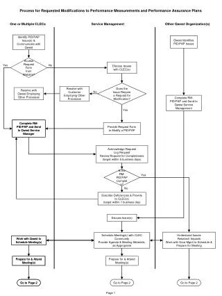
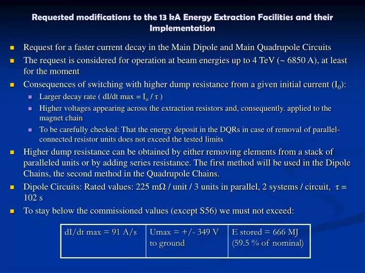
Requested modifications to the 13 kA Energy Extraction Facilities and their Implementation • Request for a faster current decay in the Main Dipole and Main Quadrupole Circuits • The request is considered for operation at beam energies up to 4 TeV (~ 6850 A), at least for the moment • Consequences of switching with higher dump resistance from a given initial current (I0): • Larger decay rate ( dI/dt max = Io / τ ) • Higher voltages appearing across the extraction resistors and, consequently. applied to the magnet chain • To be carefully checked: That the energy deposit in the DQRs in case of removal of parallel-connected resistor units does not exceed the tested limits • Higher dump resistance can be obtained by either removing elements from a stack of paralleled units or by adding series resistance. The first method will be used in the Dipole Chains, the second method in the Quadrupole Chains. • Dipole Circuits: Rated values: 225 mΩ / unit / 3 units in parallel, 2 systems / circuit, τ = 102 s • To stay below the commissioned values (except S56) we must not exceed:
Requested modifications to the 13 kA Energy Extraction Facilities and their Implementation
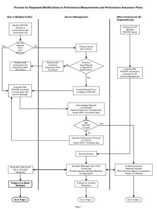
Main Quadrupole Circuits: Consists equally of three, parallel-connected units However, not disconnectable as welded structure. Consequently, additional series-connected unit needed
Present values: 7.7 mΩ / 6.6 mΩ – giving τ = 30 s (incl. cable resistance) Additional, CERN-made, plate resistor for external series-connection 1.80 mΩ / plate, 4 series-connected plates gives τ = 15 s ( 16.8 mΩ total incl. cable resistance) Thus dI/dt max = 457 A/s , compared to 310 A/s as commissioned value. Large margin to quench-back. Max voltage to ground at 6850 A: 115 V – no problem
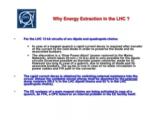
Requested modifications to the 13 kA Energy Extraction Facilities and their Implementation • One complete Prototype Quadrupole additional resistor will be ready for testing this week. • Forced-air cooled, with dissipation in the UAs. Interlocked together with the present, water-cooled unit. • Mounted on the roof of the DQSB switch. • If approved, all units can be produced and installed before 15 August.
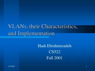
Requested modifications to the 13 kA Energy Extraction Facilities and their Implementation • Additional Proposal for the Dipole Circuits: Delay opening of one of the two switch assemblies of each dipole circuit in order to attenuate the initial voltage transient • Note: Opening of both switches is already delayed (by 330 ms w.r.t. trigger signal i.e. rupture of the quench loop) in order to assure that current decay occurs after beam ejection (large margin) • Additional delay of 500 ms of odd-point switches suggested (RC = 510 kΩ x 3 μF gives 841 ms delay) Implementation on each of the eight OOC boards in the two BCM’s of one switch assembly.