Download
1 / 12
180 likes | 706 Vues
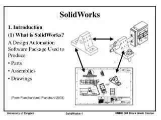
SolidWorks Simulation. Dassault Systemes 3 – D and PLM software PLM - Product Lifecycle Management Building models on Computer Engineering Analysis and Design Production Market. Solidworks. Started in 1993 3D CAD : Creating complex parts and assemblies

E N D
DassaultSystemes • 3 – D and PLM software • PLM - Product Lifecycle Management • Building models on Computer • Engineering Analysis and Design • Production • Market.
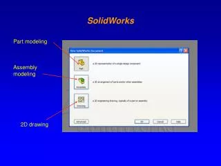
Solidworks Started in 1993 3D CAD : Creating complex parts and assemblies Modeling tools : Feature Recognition, Reverse Engineering Simulation: Engineering Analysis tools for structural, fluid and thermal analysis. 2D Drawings : Working drawings for production Data Management Presentation : Photoworks
Introduction to SolidWorks Simulation • SolidWorks Simulation is a design analysis software that is fully integrated in SolidWorks. • SolidWorks Simulation simulates the testing of your model’s prototype in its working environment. It can help you answer questions like: how safe, efficient, and economical is your design? • SolidWorks Simulation is used by students, designers, analysts, engineers, and other professionals to produce safe, efficient, and economical designs.
Traditional Design Cycle SolidWorks • Use SolidWorks to build the model. • Manufacture a prototype. • Test the prototype under various loading conditions. Instrumentation is needed in most cases. • Based on results, modify the model in SolidWorks, build a new prototype, and test it again until you are satisfied. Prototype Test Satisfied? No Yes Mass Production
Benefits of Analysis • Design cycles are expensive and time-consuming. • Analysis reduces the number of design cycles. • Analysis reduces cost by testing your model using the computer instead of expensive field tests. • Analysis reduces time to market. • Analysis can help you optimize your designs by quickly simulating many concepts and scenarios before making a final decision.
The Finite Element Method • Analytical solutions are only available for simple problems. They make many assumptions and fail to solve most practical problems. • SolidWorks Simulation uses the Finite Element Method (FEM). Analysis using the FEM is called Finite Element Analysis (FEA) or Design Analysis. • FEA is very general. It can be used to solve simple and complex problems. • FEA is well-suited for computer implementation. It is universally recognized as the preferred method of analysis.
Main Concept of Design Analysis The FEM replaces a complex problem by many simple problems. It subdivides the model into many small pieces of simple shapes called elements. CAD Model CAD Model Subdivided into Small Pieces
Main Concept of Design Analysis • The elements share common points called nodes. The behavior of these elements is well-known under all possible support and load scenarios. • The motion of each node is fully described by translations in the X, Y, and Z directions. These are called degrees of freedom (DOF). Each node has 3 DOF.
Main Concept of Design Analysis • SolidWorks Simulation writes the equations governing the behavior of each element taking into consideration its connectivity to other elements. • These equations relate the unknowns, for example displacements in stress analysis, to known material properties, restraints and loads. • Next, the program assembles the equations into a large set of simultaneous algebraic equations. There could be hundreds of thousands or even millions of these equations.
Main Concept of Design Analysis • In static analysis, the solver finds the displacements in the X, Y, and Z directions at each node. • Now that the displacements are known at every node of each element, the program calculates the strains in various directions. Strain is the change in length divided by the original length. • Finally, the program uses mathematical expressions to calculate stresses from the strains.
Static or Stress Analysis • This is the most common type of analysis. It assumes linear material behavior and neglects inertia forces. The body returns to its original position when loads are removed. • It calculates displacements, strains, stresses, and reaction forces. • A material fails when the stress reaches a certain level. Different materials fail at different stress levels. With static analysis, we can test the failure of many materials.