Download
1 / 23
230 likes | 241 Vues
Automatic t est bench for power supply modules BI Seminar. CERN, 14 th June 2019. Power supply under test: Hi- Rel DC/DC. Used on the VFC HD board 6 modules for each board. Hi- Rel DC/DC converter module for electronic boards equipped with FPGA.

E N D
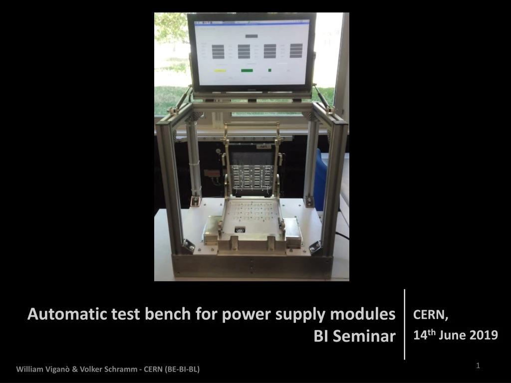
Automatic test bench for power supply modules BI Seminar CERN, 14th June 2019 William Viganò & Volker Schramm - CERN (BE-BI-BL)
Power supply under test: Hi-Rel DC/DC • Used on the VFC HD board • 6 modules for each board • Hi-Rel DC/DC converter module for electronic boards equipped with FPGA. • Designed in according with the Military/Aerospace derating rules. • Designed for long life requirements. EDMS number: EDA-02878-V3-1 William Viganò & Volker Schramm - CERN (BE-BI-BL)
Production history 2019 2018 2017 • The same company which produced the VFC HD also produced the Power Supply Module (PSM). • Before the integration onto the VFC HD it was mandatory to test each module to prevent failure of the complete board. • The test was executed at the manufacturing company. William Viganò & Volker Schramm - CERN (BE-BI-BL)
Manual test equipment • The first 1000 pieces have been manually tested one by one in the laboratory by means of a simple test bench. Oscilloscope Main power supply Frequency generator • Test board with following functions: • ON/OFF modules • VOUT setting • Variable load PC PSM under test William Viganò & Volker Schramm - CERN (BE-BI-BL)
Reasons for an automatic test • The manual test bench requires about 5 min (best case) to test a PSM, which includes: • Picking-up the PSM -> Plugging in the socket pins -> Running the test -> • Writing the report -> Unplugging the PSM -> Storing the PSM -> coffee breaks… • Performing the manual test on 7000 PSM would take a minimum of 583 working hours. With a working hour cost of about 52CHF/h, a manual test would cost at least 30K CHF. • In addition, performing a manual test has the following disadvantages: • Difficult to track faults because the PSM are too small to be equipped with a bar code (the panel is equipped with bar code). • Mechanical damage. • Quality of the data logging depends on the operator. • Difficulties in the post fault analysis. • ESD issues. William Viganò & Volker Schramm - CERN (BE-BI-BL)
Strategic decisions for the automatic test The test equipment should be portable, robust, easy to transport and use. The human interface should be simple and quick to use. Short test duration. The test equipment must be able to test a complete PCB panel with several PSM. A pre Burn-In has to be executed by stressing each PSM with high current output. A test report should be automatically created and saved on the test bench, and sent to CERN after the manufacturing. 650mm 600mm 400mm William Viganò & Volker Schramm - CERN (BE-BI-BL)
Implemented solutions for the automatic test To ensure the best mechanical compatibility, the test equipment was design in parallel with the PCB. To simplify operation of the test equipment a single switch is used to power-on the system. The test is automatically activated when the operator pull down the “handle”. A panel of 16 PSMs requires 3 seconds to be tested. Each PSM is tested sequentially. Test results are download over a Wi-Fi connection. Mechanical frame built with Bosch-Rexroth profiles. William Viganò & Volker Schramm - CERN (BE-BI-BL)
Automatic test bench - block diagram William Viganò & Volker Schramm - CERN (BE-BI-BL)
PCB paneling Power-ON LED holes Power supply module #1 Power supply module #16 Mechanical reference pins William Viganò & Volker Schramm - CERN (BE-BI-BL)
Test equipment overview Pull up pistons for PC monitor Safety Ground screw PC monitor HDMI 220VAC Power input connector PC monitor power output William Viganò & Volker Schramm - CERN (BE-BI-BL)
Test equipment overview PCB Panel under test PSM LED’s FAN location PSM global power LED Test bench power LED Teflon support for PCB panels Main power LED William Viganò & Volker Schramm - CERN (BE-BI-BL)
PCB panel interface Contact pins Aluminum base Teflon support EDA-03817 (Test equipment board) William Viganò & Volker Schramm - CERN (BE-BI-BL)
Contact pins Spring loaded pin Manufacturer: IDI Part number: S-3-A-4-G Current Rating: 5 amps continuous Spring Force: 4.0 @ 4.32mm travel Typical Resistance: < 20 mΩ Maximum Travel: 6.35mm Working Travel: 4.32mm 3D model William Viganò & Volker Schramm - CERN (BE-BI-BL)
Test bench 3D functionality William Viganò & Volker Schramm - CERN (BE-BI-BL)
Acceptance test criteria • The output voltage of the PSMs (settable with an external resistor) was set to 3.3V, and all PSM’s connected by an OR diode circuitry on the load. • The PSM output voltage has been checked against an analog comparator where thresholds were set between 2.4V and 3.2V Analog comparator PSM connections William Viganò & Volker Schramm - CERN (BE-BI-BL)
Test results • 6944 PSMs produced by Norcott (UK) equal to 434 PCB panels. • The test equipment has been delivered to Norcott with a sample PCB panels to verify the functionality. • Including operator pauses and PCB panel swapping, the average test time has been = 17 sec per panel. Plot extracted by the test equipment logging data William Viganò & Volker Schramm - CERN (BE-BI-BL)
Test result display Green = test passed Red = test fail Power supply module #1 test result display Power supply module #16 test result display • Additional manual settings were possible through the SW application. William Viganò & Volker Schramm - CERN (BE-BI-BL)
Automatic test experience • In total 16 x 5 = 80 spring loaded pins with high current flow had to be in perfect contact to allow the execution of the test. • Due to the criticality of the contact between the PSM and the test pins, in case of test failure, the test had to be repeated 3 times to be sure it was a real fault or a false negative. • Theoretical time for testing 6944 PSM (434 PCB panels) = 2h04m • Real time spent for testing = 13h03m • The main cause for the difference between the theoretical testing time and the real testing time was the repetition of the test on each panel due to the false contact between the PSM and the spring loaded pins, or due to delays caused by operators. • All “handle” actions have been recorded. William Viganò & Volker Schramm - CERN (BE-BI-BL)
Test results (1/2) • An analysis of the logging data allowed to identify PSM test slots “false negatives” in the test bench. • Corrective actions to correct the test bench slots where taken by the manufacturing company after receiving our instructions. William Viganò & Volker Schramm - CERN (BE-BI-BL)
Test results (2/2) • Power supply false negative rate: 12%. • N. of power supplies with real failures identified by the test equipment: 1 piece. • Other faults detected by the manufacturer with SMT camera: Report received by the manufacturing company about the SMT camera fault detection William Viganò & Volker Schramm - CERN (BE-BI-BL)
Conclusions –> Good practice • It is always useful to evaluate the benefits of an automatic test bench installed directly at the manufacturing company. • During the design of electronic units which are intended for mass production it should be mandatory to consider the effect of all component tolerances on the overall product reliability. • Component footprints and PCB layout design should always be designed in accordance with rules (e.g. IPC-610 class 3 for manufacturing). William Viganò & Volker Schramm - CERN (BE-BI-BL)
Conclusions -> Benefits of test benches • In case study presented– 7000 x PSM for VFC HD – the verification and check setup at the manufacturing company + the test bench ensured zero faults after the integration of the PSM’s on the VFC HD board. • The presence of the test bench at the manufacturing company had a “psychological” effect to improve the quality of the production before the test. The company was not authorized to mount PSMs or deliver VFC HD boards if they were not passing our test benches. William Viganò & Volker Schramm - CERN (BE-BI-BL)
Thank you for your attention! William & Volker William Viganò & Volker Schramm - CERN (BE-BI-BL)