Download
1 / 12
120 likes | 122 Vues
This document discusses the mechanical constraints of HCAL modules and proposes a light calibration system for the modules. It also explores the requirements for a HCAL Base Unit (HBU) and suggests possible designs for the HBU.

E N D
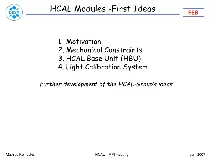
HCAL Modules -First Ideas • Motivation • Mechanical Constraints • HCAL Base Unit (HBU) • Light Calibration System Further development of the HCAL-Group‘s ideas. Mathias Reinecke HCAL – MPI meeting Jan. 2007
HCAL and FEB FEB can help in: Analog / Digital Circuit and System Design Circuit Simulation PCB Design Software (µC, Device Drivers, Control SW – C, C++, Labview) Support during Commissioning (grounding, shielding, EMC) Mathias Reinecke HCAL – MPI meeting Jan. 2007
Mechanical Constraints HCAL Half-Sector with 38 layers • Height: ~2.6 cm per layer • Width B increases with • 1.02 cm per layer • Tile Size 3 x 3 cm² • => 76000 Tiles (Half Sector) • Smallest layer: 74 x 220 cm² • Largest layer : 96 x 220 cm² Layer Concentrator HCAL Base-Unit (HBU): - each HBU is 12 tiles (36 cm) deep - always 6 HBUs in a row cover the full sector length - 2 or 3 HBU-rows of different widths cover a layer Mathias Reinecke HCAL – MPI meeting Jan. 2007
Mechanical Constraints Requirements for a HCAL Base-Unit (HBU) from the Barrel‘s mechanics: • As large as possible (assembly time) • As thin as possible (barrel diameter) • Easy de-/installation of single units • (repair) • -If possible: not larger than 43cm • (PCB assembly, unit construction, stability) • -Rail System needed (Sector Orientation) • -Minimize dead area • Number of SiPM inputs per ASIC ??? • Request of LAL: Multiples of 18 HCAL: 2 x 8 Sectors 2,432,000 Tiles Mathias Reinecke HCAL – MPI meeting Jan. 2007
How to Fill the Sector‘s Layers Depths of all HBUs: 12 tiles (36 cm), 6 HBUs = 216cm Sector layer widths: 24 tiles (72cm) to 33 tiles (99cm) Needed HBU widths to fill all sector layers: 54‘er HBUs of: 8, 9, 11, 12 and 13 tiles width or 72‘er HBUs of: 6, 8, 10, 11 and 12 tiles width. Switch off unused inputs !! Mathias Reinecke HCAL – MPI meeting Jan. 2007
Tiles in the HBU Standard Tile: 30 x 30 x 3 mm³ Mechanics Tile: HBU Interconnection and Rail System mounting 6mm bolt with M3 thread inside Tile Alignment Pins ~ 2mm height SiPM Carrier Mathias Reinecke HCAL – MPI meeting Jan. 2007
HBU – How could it look like ? Reflector Foil 100µm Polyimide Foil 100µm Top Plate 300µm ASIC LQFP-144 1.4mm high PCB 1mm HBU Interface 1mm gap Rail System 2mm/1mm Component Area: 1.7 mm high HBU height: 6.9mm (6.0mm without covers => absorber) SiPM Bolt with inner M3 thread welded to bottom plate Bottom Plate 600µm Tile 3mm Steel Plate Mathias Reinecke HCAL – MPI meeting Jan. 2007
HBU height – Component Area There is still room for a few 100µm. -HBU Interconnection (1.3mm): • SiPM Solder Pins (1.5mm): • 1mm possible? • -Rail System (2mm) • is 2mm sufficient? • ASIC (1.4mm): • 1mm: max 100 pins • -Blocking Capacitor (1.1mm): • 0.8mm: max 4.7µF Mathias Reinecke HCAL – MPI meeting Jan. 2007
HBU Insertion (Top View) • HBU Interconnection: • Close Mechanical Tabs • Close Electrical Conn. • Push into Sector Layer • Repeat 1-3: • Six HBUs in a row. Tile PCB Steel Absorber Rail System ASIC Mathias Reinecke HCAL – MPI meeting Jan. 2007
Light Calibration System Use ‚Distance‘ of Single-Photon Peaks for calibration (LED light output level not critical), couple LED light into the Tile Alignment Pins: LED PCB Reflector Foil One LED per tile : No fibers needed. One LED per HBU : No fibers between modules (HBUs) Mathias Reinecke HCAL – MPI meeting Jan. 2007
Temperature / Power Dissipation From P. Göttlicher • No. channels: 1000 / m² • Train: 1ms length in 5Hz rate • Pow. Diss.: 40µW / channel • (25µW ASIC, 15µW HV) • Time constant of heat effects: • a = ~6 days, 0.33K (z=0) • Current consumption: • 3 A/plane (during train) Mathias Reinecke HCAL – MPI meeting Jan. 2007
Conclusions • Very first idea about how things could look like. • Nothing is fixed. • Concept is basis for further discussions. Mathias Reinecke HCAL – MPI meeting Jan. 2007