Download
1 / 18
180 likes | 310 Vues
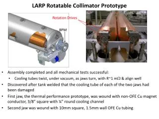
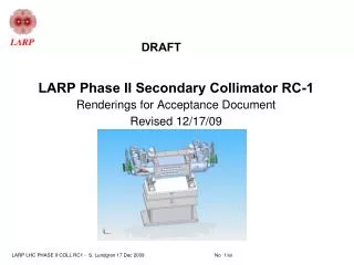
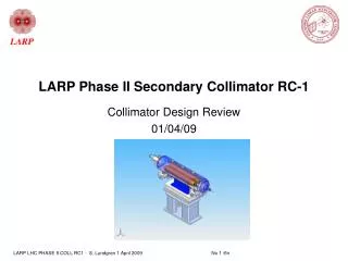
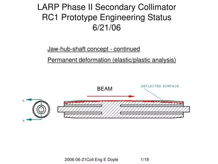
LARP Phase II Secondary Collimator RC1 Prototype Engineering Status 6/21/06. Jaw-hub-shaft concept - continued Permanent deformation (elastic/plastic analysis). Overview. Review Baseline jaw Central stop Concept Discuss RC1 baseline deflection reference Refine baseline

E N D
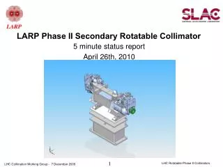
LARP Phase II Secondary Collimator RC1 Prototype Engineering Status6/21/06 Jaw-hub-shaft concept - continued Permanent deformation (elastic/plastic analysis) 2006-06-21Coll Eng E Doyle 1/18
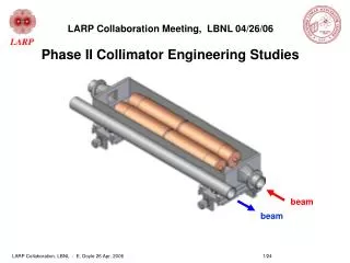
Overview • Review • Baseline jaw • Central stop Concept • Discuss RC1 baseline deflection reference • Refine baseline • Shorter pitch cooling helix • Solid core • New jaw-hub-shaft concept • Eliminate central stop? • Plastic deformation 2006-06-21Coll Eng E Doyle 2/18
Review: Baseline Jaw Performance (deflections referred to edge of jaw - Note this is not a realistic mounting possibility) Exceeds spec, or other possible problem as noted V V Baseline: hollow Cu, 25mm wall, helical cooling - 5cm pitch Exceeds Allowed Deflections All temperature simulations based on 20C supply. For CERN 27C supply add 7 to all temperature results. CERN max water return temp 42C 2006-06-21Coll Eng E Doyle 3/18
Two concepts for reducing deflection • Central aperture stop • Separate shaft and jaw 2006-06-21Coll Eng E Doyle 4/18
support dx=394 mm Spec: 25mm support Bending exceeds 25um spec => Compromise: Central aperture stop controls deflection - causes jaw to deflect away from beam – Note: this is idealized stop Steady State operation (End supports as modeled) 86C • Idealized Central Aperture Stop • Swelling neutrallized • Bending neutralized More realistic: shaft support -Swelling toward beam -Bending toward beam 2006-06-21Coll Eng E Doyle 5/18
RC1 Concept as presented to reviewers: Flexible end supports with central aperture stop Leaf springs allow jaw end motion up to 1mm away from beam Stop prevents thermal bowing of jaws from intruding on minimum gap Local swelling not controlled 2006-06-21Coll Eng E Doyle 6/18
V Real aperture stop allows some swelling Stop hidden out of beam’s reach at 45o Swelling not fully neutralized – note bulge of hot region between stop and aperture. Stop Peak temperature due to beam heating 2006-06-21Coll Eng E Doyle 7/18
Jaw-hub-shaft - Eliminate Central Stop? shaft hub jaw • Hub acts as a heat sink near peak temperature location, lowering peak temperature, reducing gradient and bending. • Both ends of jaw deflect away from beam. (Note: swelling component of deflection is not corrected - ~ the same as for stop @ 45o.) • Max deflection toward beam reduced if the shaft deflection can be minimized • Cooling coils embedded in I.D. of jaw. 2006-06-21Coll Eng E Doyle 8/18
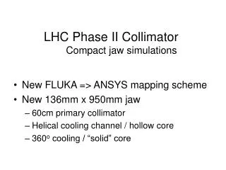
Advances since RC1 Baseline more cooling solid core 2006-06-21Coll Eng E Doyle 9/18
Evolution of jaw-hub-shaft25mm deep cooling tubes SS 1hr beam Transient 10sec @12min beam RC1 – not a practical support scheme More realistic Next for jaw-hub-shaft: Alternative materials to reduce shaft deflection Note reduced shaft end deflection – a positive result if stop is used 2006-06-21Coll Eng E Doyle 10/18
Alternative Shaft MaterialsShaft supported case -Slight Improvement Deflection is combo of bending & swelling 2006-06-21Coll Eng E Doyle 11/18
Alternative Shaft MaterialsCentral stop-supported case - No Improvement Note: values in table manually adapted from simulation results based on jaw edge or shaft end supports. Stop located in mid-jaw at 45 degrees from point closest to beam. 2006-06-21Coll Eng E Doyle 12/18
Evaluate jaw-hub-shaft25mm deep cooling tubes New Baseline SS 1hr beam 4x 2x Transient 10sec @12min beam Note: deflection means deviation from straight (in um). Eff length is length of jaw (in m) deflected <100 um compared to maximum deflection point. With stop con: 2x deflection pro: 75% reduction of shaft motion Shaft support only con: 4x deflection pro: simpler mechanism, same control architecture as Ph I 2006-06-21Coll Eng E Doyle 13/18
Permanent Deformation Initial condition: 1 hr beam lifetime heating rate. Transient: 10 seconds heating at 12min beam lifetime rate followed by 50 seconds cooling. Copper Glidcop AL15 2006-06-21Coll Eng E Doyle 14/18
Permanent Deformation Permanent bending of jaw after one transient heating cycle. Deflection is concave as seen from beam. Glidcop AL15 effectively prevents plastic deformation. 2006-06-21Coll Eng E Doyle 15/18
Further refinements • Optimize hub length, location • Hub region solid Cu, two stub shafts of alternative material, butted to hub • Shallow cooling tubes (~15mm) • Glidcop only where necessary – outer radii 2006-06-21Coll Eng E Doyle 16/18
Xtra Slide 2006-06-21Coll Eng E Doyle 17/18
Evolution of jaw-hub-shaft25mm =>10mm deep cooling tubes SS 1hr beam Transient 10sec @12min beam SS Transient 2006-06-21Coll Eng E Doyle 18/18