Download

1 / 30
320 likes | 523 Vues
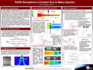
Numerical Investigations on a Hot Jet in Cross Flow. Directeurs de thèse: P. Millan, ONERA S. Deck, ONERA. Encadrants: F. R. Menter, ANSYS H. Bézard, ONERA M.-J. Esteve, AIRBUS. Benjamin Duda 3e année DMAE/DAAP Bourse CIFRE. Outline. Introduction Motivation & Objectives Methodology

E N D
Numerical Investigations on a Hot Jet in Cross Flow Directeurs de thèse: P. Millan, ONERA S. Deck, ONERA Encadrants: F. R. Menter, ANSYS H. Bézard, ONERA M.-J. Esteve, AIRBUS Benjamin Duda 3e année DMAE/DAAPBourse CIFRE
JDD 2012 Outline • Introduction • Motivation & Objectives • Methodology • Test Case Definition • Scale-Resolving Simulations • Validation • Physical Analysis • Industrial Application • Conclusion & Outlook
JDD 2012 Motivation & Objectives • Jet in cross flow appears at air system exhausts • Turbulent, transient and fully three dimensional flow including heat transfer at high Reynolds number • Complex interaction of large and small scale structures depending on blowing ratio rjWj /(r∞U∞) • Prediction of flow and temperature field for aircraft safety and weight reduction • Flow analysis Composites Bulkhead Fan Thermal shield Lip Scoop Grid U∞ Wj
JDD 2012 Generic Jet in Cross Flow Configuration
JDD 2012 Boundary Conditions & JICF Similarity Parameters • Wind tunnel inlet • velocity: 47.18 m/s (Ma = 0.14) • total temperature: 291 K • turbulence intensity = 0.5 %, mt/m = 10 • Hot air supply • mass flow: 0.03542 kg/s • total temperature: 353 K • turbulence intensity = 0.5 %, mt/m = 10 • Wind tunnel outlet • static pressure • Mock-up walls • no-slip boundary condition, adiabatic • Wind tunnel walls • free-slip boundary condition
Scale-Resolving Simulations JDD 2012 • Jet in cross flow simulations require the resolution of at least a part of the turbulence spectrum • Pure Large Eddy Simulations for high Reynolds number and wall-bounded flows are too expensive • Focus on hybrid turbulence models and zonal formulations: • Resolve large, energy containing and geometry dependent vortices • Model smaller and more universal turbulent structures • Stable flow regimes with RANS Idealized spectrum ofturbulence kinetic energy log E energy transfer production resolved modeled log k RANS ← Hybrid → LES ↔ DNS Page 6
JDD 2012 Categorization of Turbulence Modeling Approaches Scale-Resolving Simulations IntegratedApproach SequentialApproach
JDD 2012 Turbulence Modeling Approaches • Integrated approach • Single transient calculationof entire domain withlocalresolution of turbulencescales • Sequential approach • Two consecutivecalculations • Steady RANS in entire domain • Extraction of subdomain and boundary conditions • Scale-resolving simulation only in subdomain
JDD 2012 Categorization of Turbulence Modeling Approaches Scale-Resolving Simulations IntegratedApproach SequentialApproach Hybrid Zonal ELES SAS DDES
JDD 2012 Integrated Hybrid Approach I Scale-Adaptive Simulation (SAS) • Introduction of additional source term QSASto w-equation in SST model • Active in areas with inherent flow instabilities and sufficient grid refinement • Sensor for instability is von Kármán length scale LvK • Production of w leads to decrease of eddy viscosity mt • No explicit dependence on grid spacing D • k-wSST capability in stable flow regimes, e.g. attached boundary layers
JDD 2012 Integrated Hybrid Approach II Delayed Detached Eddy Simulation (DDES) • DES: Blending of RANS (k-w SST) and LES (dynamic k subgrid scale) formulation • LES in regions with CDESD < Lt, RANS elsewhere • Explicit dependence on grid spacing D • Delayed formulation: Attached boundary layers are forced to RANS regime with help of shielding functions
JDD 2012 Integrated Zonal Approach Embedded Large Eddy Simulation (ELES) • Definition of a spatially fixed fluid zone where scale resolution using LES is desired • Rest of domain is calculated using (U)RANS formulation • Conversion of turbulent kinetic energy content from RANS models to resolved turbulent fluctuations in LES zone • Vortex generation method at RANS-LES interface RANS zone LES zone U∞ Model interface (conformal or non-conformal mesh interface)
Resolution Requirements & Meshing Strategies JDD 2012 • Boundary layer: accuracy and heat transfer require y+<1 • Jet and cross flow interaction region: • Grid spacing D and time step Dt small enough for scale resolution • Ideally isotropic mesh due to unknown vortex orientation • Strategies: 12.9x10⁶ cells 13.1x10⁶ cells 21.0x10⁶ cells • Hexahedral mesh based on multi-block approach • Hybrid Cartesian mesh with prismatic & hexahedral inflation layers • Hybrid tetrahedral mesh with prismatic inflation layers Page 13
Scale Resolvability of Turbulence Models JDD 2012 Judge scale resolution qualitatively withQ-criterion:Q=0.5(|Wij|2-|Sij|2) SAS DDES ELES URANS Page 14
Time Averaged Temperature Distribution I JDD 2012 Turbulence models (on hex) • Good agreement in far field • Slope of SAS and DDES agree well with small offset in near field • Incapability of URANS to resolve scales explains poor mixing and strong temperature gradient Meshing strategies (with SAS) • Generally very good agreement • Small underestimation for hex and cart mesh • Tet mesh is closest to exp data due to smaller cells I Page 15
Time Averaged Temperature Distribution II JDD 2012 Turbulence models (on hex) • Lateral spreading of temperature in good agreement with all three SRS • Poor URANS prediction due to unphysical damping of lateral jet wake movement Meshing strategies (with SAS) • Generally very good agreement • Small underestimation for hex mesh at center II Page 16
2nd Order Time Statistics JDD 2012 z x y EXP SAS Hexahedral mesh Page 17
Spectral Analysis JDD 2012 Hexahedral mesh with identical time step Dominant frequency at StD = 0.14 is predicted correctly for SAS, DDES and ELES Very broad peak for URANS No high frequency contribution in URANS simulation due to incapability of resolving turbulent fluctuations Page 18
Time Step Study (SAS on hex mesh) JDD 2012 • Improving agreement with decreasing time step • Small differences for 1st order time statistics • Good prediction of dominant frequency for all time steps • But different contribution to energy content of fluctuation since magnitude of spectral peak differs by a factor of 2 Page 19
Stationary Flow Topology I JDD 2012 Recirculation zone consists of two connected upright vortices RANS resemblance Instability causes stagnation point (SP) to oscillate and induces dynamics SP Page 20
JDD 2012 POD for Jet in Cross Flow Configuration • Memory requirement: 22GB • Time consumption: • 35min for data import • 35min for POD (u, v, wand T) • 30min for LRA (r=2) POD box with 440,000 sampling points (Resampled from 300 SAS time steps on hex mesh)
JDD 2012 POD Modes • First mode contains ‘mean’ flow • Higher order modes contain representation of flow dynamics • 2nd mode shows wake meandering • Temporal evolution, shape and spatial spreading time coefficient ak=2(Dt) ! StD = 0.14 ! orthonormal function fk=2(x,y,z) for y-velocity component
JDD 2012 Low-Rank Approximation With First Two Modes Interaction of turbulent scales leads to ‘chaotic’ temperature field Originaltransient SASdata Reconstructeddata clearlyshows wakemeandering
Hairpin Vortices JDD 2012 Q Criterion DDES w u jet6 jet5 • Most pronounced for DDES • High dynamics of wake lead to strong deformation of structures • Vortices entrain cold cross flow fluid and are important for mixing Page 24
Preliminary Study for Real Aircraft Application JDD 2012 5 drop shaped ejectors in a row on generic configuration Hexahedral mesh with 25.5·106 cells SAS model Page 25
Animation of Turbulent Structures JDD 2012 Page 26
Thermal Efficiency for Multiple Jets in Cross Flow JDD 2012 SAS SAS EXP Page 27
Process for Industrial Application I JDD 2012 • RANS calculation of aircraft with clean nacelles • Extraction of results on boundaries of subdomain • Mesh generation in subdomain with real exhaust geometry • SAS calculation only in subdomain with fixed RANS boundary conditions
JDD 2012 Process for Industrial Application II
Conclusion Validation of scale-resolving turbulence models Analysis of transport and mixingphenomena Application to industrial configuration Finalising simulations and compilation of dissertation Conferences & Publications: 7th International Symposium on Turbulence and Shear Flow Phenomena (TSFP-7), 28 - 31 July 2011, Ottawa, Canada European Turbulence Conference (ETC 13), 12 -15 September 2011, WarsawPoland Invited speaker at ANSYS Turbulence Seminare, 6 December 2011, Munich, Germany AIAA Journal publication in perparation JDD 2012