Download
1 / 58
580 likes | 664 Vues
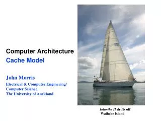
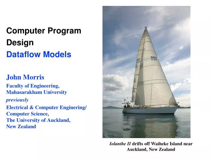
Computer Program Design Dataflow Models John Morris Faculty of Engineering, Mahasarakham University previously Electrical & Computer Enginering/ Computer Science, The University of Auckland, New Zealand. Iolanthe II drifts off Waiheke Island near Auckland, New Zealand. Self Introduction.

E N D
Computer Program Design Dataflow Models John Morris Faculty of Engineering,Mahasarakham University previously Electrical & Computer Enginering/Computer Science, The University of Auckland,New Zealand Iolanthe II drifts off Waiheke Island near Auckland, New Zealand
Self Introduction • John Morris, PhD(Sydney) • Before coming to Mahasarakham ..Assoc Professor, Electrical and Computer Engineering/Computer Science, University of Auckland, New Zealand (now part-time) • Current study
Brief CV • PhD – University of Sydney, Australia – optical spectroscopy • Post-doctoral: • National Research Council of Canada, Ottawa • University of Tokyo (東京大学), Japan • University positions • University of Melbourne, Physical Chemistry • University of Tasmania, Computer Science • University of Western Australia, Electrical Engineering • University of Auckland, Electrical and Computer Engineering/Computer Science • Visiting • Institute for Molecular Science (分子科学研究所), Okazaki, Japan • Osaka University(大阪大学), Japan • MIT, Cambridge, USA • Case Western Reserve University, Cleveland, USA • ChungAng University (중앙대학교), Seoul, Korea • Kyung-pook University(경북대학교), Daegu, Korea • Shandong University(山东大学), Jinan, China • Kaohsiung National University, Kaohsiung, Taiwan
Research Interests Just in case you’re interested • Real-time stereophotogrammetry • Attempting to mimic capabilities of human-eye brain combination • Use two cameras connected to an FPGA or a GPU to generate high resolution 3D ‘images’ of a scene in real-time • Accelerating computations with attached processors – FPGA or GPU • Photo-realistic rendering for special effects in movies
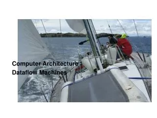
When not working … Iolanthe II Track – New Zealand toNew Caledonia, 2012 Channel Island,Entrance to Hauraki Gulf Hauraki Gulf,Auckland Arriving Noumea,New Caledonia, 2012
Iolanthe III Singapore – Malaysia – Koh Samui – Koh Tao – Sattahip, January 2-20, 2013 in Ocean Marina, Jomtien now!
Racing … Iolanthe III Iolanthe III races every month from Jomtien, ChonburiNext race: August 9 – Sign up now!
My Thai is very limited … • These words are not very useful for talking about computers .. • So my lectures are 99.9% English!
Advanced Thai Beware: Do not use this word in my class – your ajarn will understand it
Questions? • Ask questions at any time! • There are NO silly questions!! • Only failing to ask a question is silly! • If you didn’t understand, there are certainly other students in the room that didn’t understand too! • They will be very happy for you to ask!! • Not confident in English? • You will get better if you try! • Ask in Thai anyway – someone will be able to help! • To encourage you to ask questions, the student who asks the first question about the material of the course will receive a bottle of excellent Australian red wine!
Computer Structure • Modern computers are based on the von Neumannorstored program architecture • ‘Architecture’ of a computer describes • its structure and • how the parts are linked together Basic components of avon Neumann machine
John von Neumann • 1903 – born as Neumann János Lajos, December 28 in Budapest, Austria-Hungary • 1933 - Professor in Mathematics at Princeton University, New Jersey, USA changed his name to more American, John von Neumann • Many contributions to mathematics and quantum physics • Realized that a computer could store both program and data – the model for most modern computers!
Computer Structure • In a von Neumann computer, the Central Processing Unit (CPU) has a memory which contains both instructions and data • CPU fetches instructions which determine the calculations to be made on data (numbers) in the same memory Basic components of a von Neumann machine
Computer Structure • Memory is usually a linear array of binary bytes • Byte • In modern systems, a byte is 8 binary bits • Words • Bytes are grouped into words eg8 bytes = 64 binary bits in a modern system • Address • Each byte is given a number (its address) from 0to 2n-1 • If n = 32, the memory contains 232 = 4,294,967,296 • Commonly called 4 GB (GigaBytes) • 4 GB = 4 × 1024 × 1024 × 1024 = 4 × 210 × 210 × 210
Computer Memory 1048574 • Linear array of binary bytes • Address Example • Memory contains • 220 = 1,048,574 bytes • 1MB (MegaBytes) • 1 MB = 1 × 1024 × 1024 = 1 × 210 × 210 bytes • Address range • 0 to 1,048,575 • 0 to 220-1 • Each memory location holds • Instructionor • Data 1048572 1048570 1048568 1048566 8 6 4 2 0
Writing a program Steps • Write a solution to your problem in a High Level Language such as C, C++ or Java • Use a compiler to convert the program to machine code • Transfer the machine code to memory • Tell the computer the start address of your program • Input data • Calculate …………….. • Collect results
High Language Code • Simple program to read a large set of numbers and calculate the average • C language #define B_LEN 16 int main() { float x, sum, average, count; char buf[B_LEN]; count = 0.0; do { fgets(buf,B_LEN,stdin); x = atof( buf ); if ( x < 0.0 ) break; sum = sum+x; count = count + 1; } while ( x > 0.0 ); average = sum/count; fprintf( stdout, “Average: %f\n”, average ); }
High Language Code Working storage • Most of this program is easy to understand • Comments have been added so that you can understand the calculation #define B_LEN 16 int main() { float x, sum, average, count; char buf[B_LEN]; count = 0.0; // Set count to zero do { // Repeat reading numbers fgets(buf,B_LEN,stdin); // Read typed numbers x = atof( buf ); // Convert to binary if ( x < 0.0 ) break; // Check if finished sum = sum+x; // Add numbers in sum count = count + 1; // Count how many read } while ( x > 0.0 ); // Stop if –ve input average = sum/count; // Calculate average fprintf( stdout, “Average: %f\n”, average ); } // Print average and end
Loading program into memory MEMORY Working storage Data or Variables Each variable allocatedto a memory location buf 847 average Datastore 0 0 count sum 0 0 x #define B_LEN 16 int main() { float x, sum, average, count; char buf[B_LEN]; count = 0.0; do { fgets(buf,B_LEN,stdin); x = atof( buf ); if ( x < 0.0 ) break; sum = sum+x; count = count + 1; } while ( x > 0.0 ); average = sum/count; fprintf( stdout, “Average: %f\n”, average ); } Compiler Text Computerinstructions Instructionstore
Lab exercise MEMORY Working storage Data or Variables Each variable allocatedto a memory location Words 32 bits or 4 bytes Each character 8 bits So 4 characters in each 32 bit word Datastore rld o wo Hell TurboC Compiler Text Object Computerinstructions int main() { printf( “Hello world\n” ); } • TurboC2 steps • Source object • Object machine code 1 Instructionstore 2
Compilers • Most compilers have two phases • Compiler • Converts source (program text) to intermediate form • One source file may only be part of a program, eg • Factorial function • Sine function • … • Linker • ‘Link’ as in links in a chain ( โซ่ ) • Linker links (joins) all the functions together to make a program First useful word I know in Thai
Designing programs • Before building a bridge, aircraft, large building, factory, …. • Engineers will carefully design all parts of the system • Usually by preparing extensive diagrams of every part • Computer programs must be designed in the same way!
Engineering Design All design starts with drawings .. Simple parts Complex components
Engineering Design All design starts with drawings .. Complete Structures
Designing programs • Computer programs must be designed in the same way! • We use formal diagrams called Dataflow diagrams
Data flow diagrams Dataflow Diagram • Example c = ( a2 + b2 ) • Inputs: a, b • Output: c • Computation c a b
Data flow elements Dataflow Diagram • Dataflow • Data • a and b • flowsinto computation blocks • ×, +, • and • out to the next • Final output is result c = ( a2 + b2 )
Data flow elements Dataflow Diagram Input data Variables Data flows along Arcs Circles are Computations Output data Result
Data flow elements Dataflow Diagram • Dataflow • Data • a and b • flowsinto computation blocks • ×, +, • and • out to the next • Final output is result c = ( a2 + b2 ) Copy atwice a2 b2 a2 + b2 (a2 + b2)
Data flow elements Dataflow Diagram • Example • Volume of a cone • V = 1/3 r2h Copy rtwice Inputs: r, h Constants:0.333.., p r2 p/3 p/3 r2 p/3 r2 h Output: V
Data flow components • Low level (simple) diagrams • If we designed everything at this low level, we’d never finish any design • It would be like this .. and need several tonnes of paper !! Problem: Find the engineer? ?? (A bit like the Immigration Office!)
Data flow components • Diagrams can be simple to complex .. • Low level: +, -, ×, ... • Basic functions: sqrt, cos, … • Complex operations: integration, .. • System level: control a robot, simple phone, • Complex systems: aircraft systems, smart building, smart phone, … • We can build complex diagrams from simple ones ..
Computing sin(x) • Many computations require mathematical functions • sin, cos, log, exp, …. • Usually computed only when needed • sine computed by this equation Usually, this expressionis truncated after ~10 termsbecause xn << n! for large n
Function operations • First we need the factorials3!, 5!, 7!, …. • We can show how to computethese with simple diagrams • This diagramshows the usualcalculation of the factorials • 2! 3! 4! 5! ….
Low level operations Factorial calculation • To add this to a more complex(higher level) diagram • We hide the internal detail • Just show the outputs • 2! 3! 4! 5! …. Factorial function (no internal detail!)
Calculating sin(x) • sin function
Data flow elements Dataflow Diagram • Example • ex can be computed with the formula: • Only 5 terms shown – more may be needed to obtain higher accuracy ex
High level function • Again, we would builda high level function • Hides the detail! • Allows designer to focuson the important problem • Re-use • Re-use = use + re- (again) = use again • Now we have several example of the re-use idea! • Solve a problem once, re-use that solution to solve another problem
Re-use and Patterns • Re-use • Re-use = use + re- (again) = use again • Now we have several example of the re-use idea! • Solve a problem once, re-use that solution to solve another problem • In English, we have a saying • ‘Don’t re-invent the wheel’
Re-use and Patterns • Patterns • Observe that the sin(x) function and the e(x) function have similar structure! • I built the e(x)DFD (data flow diagram) by • Copying the sin(x) one and • Modifying it • Re-use and patterns • Save time • Reduce probability of error • More efficient programs • Use an efficient solution to one problem to solve a similar one!
Decisions • Many computations must choose eg min or max? • Input a, b ? • Which is min? max? • Use a diamond surrounding a choice • Example • Rectangle must be uprightfor the next step in a calculation • Diamond contains a condition – h > w ? • Edges are marked Y or N
Repetitive operations • One advantage of computers is • Precise, fast repetition of large numbers (millions or more) of calculations which are • Boring • Complex • Repetitive • Error prone • Simple diagrams shown already are not powerful enough for efficient design • We need additional symbols! • Summation example • Sum n numbers and calculate max, min, average
Repetition • Calculation of sum • Iterative computation • Inputs • Stream of x values • n – number of inputs • Values recycled through+ modules • Decision ‘cnt > n’terminates sum when cnt > n • Final output: sum Sum is re-cycledand becomes thenew input
Building larger blocks • Iterations make functions like • sin, cos, .. • more compact
Data – Sources and Sinks • To complete a system diagram, add • Sources or Inputs of data • Devices • Keyboards • Discs • Data acquisition devices • Communication links • Networks • Wireless • Memory • Stored in the computer’s memory by previous programs
Data – Sources and Sinks • Sinks or Outputs for data • Devices • Displays • Discs • Motors, actuators, … • Anything that controls a machine, vehicle, robot, … • Communication links • Networks • Wireless • Memory • Stored in the computer’s memory for use by the next program
Electrical problem • You want a simple program to compute the voltage across a resistor when a current flows • Ohm’s Law: V = I * R • So make a program that • Inputs • I • R • Outputs • V • It should also tell the user when to input I and R /*Ohm Law Program*/ #include <stdio.h> #include<conio.h> main() { float i,r; clrscr(); printf("Ohm Law Program\n"); printf("Enter Current ="); scanf("%f",&i); printf("Enter Resistance ="); scanf("%f",&r); printf("Voltage=i*r=%f Volt",i*r); getch(); }
Electrical problem Input and output devices • DFD • Inputs from keyboard • I • R • Outputs to screen • V • Prompts to direct user to screen
Electrical problem • In C, this DFD becomes this program – see lab this afternoon! /*Ohm Law Program*/ #include <stdio.h> #include<conio.h> main() { float i,r; clrscr(); printf("Ohm Law Program\n"); printf("Enter Current ="); scanf("%f",&i); printf("Enter Resistance ="); scanf("%f",&r); printf("Voltage=i*r=%f Volt",i*r); getch(); }
Sources and Sinks – Input and Output All the rectangles or open boxes are sources or sinks No standards for sources andsinks Use an appropriate symbol!! Pictures representing thedevice