Download

1 / 30
310 likes | 551 Vues
Interfacing of LCD with µP. LCD (Liquid crystal display). A liquid crystal display ( LCD ) is a thin, flat electronic visual display that uses the light modulating properties of liquid crystals (LCs). Applications:-

E N D
Interfacing of LCD with µP Temperature control using ADC
LCD (Liquid crystal display) A liquid crystal display (LCD) is a thin, flat electronic visual display that uses the light modulating properties of liquid crystals (LCs). Applications:- Used in computer monitors , televisions , instrument panels, video players, gaming devices, clocks , watches, calculators , and telephones etc. Temperature control using ADC
Pin diagram of LCD 1.Vss – Gnd 2.Vcc - +5V 3.Vee - Contrast control 4. RS - Register select [RS=0: Command, RS=1: Data] 5. RW - Read / Write 6. EN - Enable pulse. 7. D0 - Data bus LSB 8. D1 ........ ........ 14. D7 - Data bus MSB. 15 & 16 - Backlight. Temperature control using ADC
ADC 0808 1. A, B, C addresses to select IN0-IN7 2. activate Address latch enable (ALE) to latch in the address. 3. SC is for Start Conversion. 4.EOC is for End of Conversion 5. OE is for Output Enable. 6. The output pins D0-D7 provides the digital output from the chip. 7. Vref (-) and Vref (+) are the reference voltages
SELECTING AN ANALOG CHANNEL How to select the channel using three address pins A, B, C is shown in Table below:
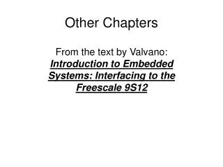
Interfacing of ADC0808 with µP Input to ADC0808- • SOC • OE • A,B,C • ALE Output for ADC0808- • EOC • D0-D7 PORT A - D0-D7(input) PORT B - SOC(PB0) - OE(PB1) - A,B,C(PB2,PB3,PB4) PORT C - EOC(PC0) CWR=99H Addresses for ports A,B,C and CWR=60H,61H,62H,63H
Interfacing of ADC0808 with µP IN0 IN1 IN2 IN3 IN4 IN5 IN6 IN7 PA0-PA7 D0-D7 ALE PB0 PB1 PB2 PB3 PB4 SOC OE A B C 8255 ADC 0808 PC0 EOC Clock generator CLK
The sequence and bit pattern required to give control signals. The steps involved will be as:
Program:- MVI A,99H OUT 83H MVI B,00H LOOP: MOV A,B ANI 1CH ORI 01H OUT 81H ANI 1CH OUT 81H UP: IN 82H ANI 01H CPI 01H JNZ UP MVI A,02H OUT 81H IN 80H OUT DISPLAY CALL DELAY MOV A,B ADI 04H MOV B,A JMP LOOP
Pin description • The supply range is from +5V to +15V, while Vref may be any where between -10V to +10V. • The maximum analog output voltage will be any where between -10V to +10V, when all the digital inputs are at logic high state. • Usually a zener diode is connected between OUT1 and OUT2 to save the DAC from negative transients. • An operational amplifier is used as a current to voltage converter at the output of AD to convert the current out put of AD to a proportional output voltage.
Program:- • Generate square wave :- MVI A,80H OUT 83H UP: MVI A,00 OUT 80H CALL DELAY MVI A,F0H OUT 80H CALL DELAY JMP UP
Generate Triangular wave:- MVI A,80H OUT 83H MVI B,00H AGAIN: MOV A,B UP: OUT 81H CALL DELAY INR B MOV A,B CPI FFH JNZ UP BACK :DCR B MOV A,B OUT 81H CALL DELAY CPI 00H JNZ BACK JMP AGAIN
Generate saw-tooth wave:- MVI A,80H OUT 83H AGAIN: MVI B,00H JMP AGAIN MOV A,B HLT UP: OUT 81H CALL DELAY INR B MOV A,B CPI FFH JNZ UP
Temperature control Temperature control using ADC
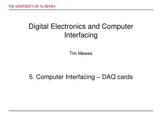
. Flow chart • . START Initialize 8255 CALL CONVERSION Turn heater on Is Temp > SET Temp Turn heater off . Temperature control using ADC
Diagram Sensor Heater Temperature control using ADC
Control Word The control word for the PPI is – 1 0 0 1 0 0 0 1 i.e., 91H. Temperature control using ADC
Program: MVI A, 91H OUT CR BEGIN: CALL CONVERSATION CPI 41H JC NEXT MVI A, 0EH OUT CR JMP BEGIN NEXT: MVI A, 0FH OUT CR JMP BEGIN Temperature control using ADC
Conversion Subroutine: CONVERSION: MVI A,00H OUT PB ; Send address to select IN0 MVI A,08H ;Latch address by giving ALE High OUT PB MVI A,18H OUT PB ; Make SOC High MVI A,08H OUT PB ; Make SOC Low MVI A,00H OUT PB ; Make ALE Low LOOP: IN PC ANI 01H JZ LOOP ; Wait for EOC IN PA RET ; Return value and store Accumulator Temperature control using ADC
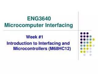
Interfacing Circuit Temperature control using ADC
The load, in this case a heater, is a device which operates under 230V ac. The control signal from the microprocessor through the peripheral interface is of 5V magnitude. A solid state relay device is used to interface the control signal with the load. Temperature control using ADC
Program:- MVI A,91H OUT 03 L2: CALL CONVERSION CPI 80H JC L1 MVI A,0EH OUT CWR JMP L2 L1: MVI A,OFH OUT CWR JMP L2 SUBROUTINE conversion : MVI A,00H OUT PB MVI A,08H OUT PB MVI C,0AH L3: DCR C JNZ L3 MVI A,18H OUT PB MVI A,08H OUT PB MVI A,00H OUT PB L4: IN PC ANI 01H JZ L4 IN PA RET Temperature control using ADC