Download
1 / 46
480 likes | 866 Vues
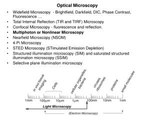
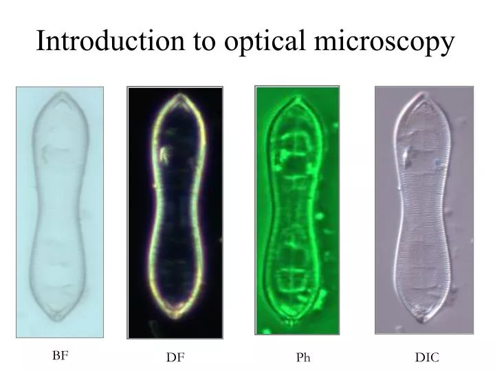
Introduction to optical microscopy. BF. DF. Ph. DIC. Introduction to optical microscopy. Some basic optics Properties of lens Types of illumination Resolution Contrast Phase contrast Differential Interference Contrast. Contrast techniques in optical microscopy.

E N D
Introduction to optical microscopy BF DF Ph DIC
Introduction to optical microscopy • Some basic optics • Properties of lens • Types of illumination • Resolution • Contrast • Phase contrast • Differential Interference Contrast Contrast techniques in optical microscopy Thanks to Guy Cox (Electron Microscope Unit, University of Sydney) for contribution of many of these slides
Refraction • Direction change of a ray of light passing from one transparent medium to another with different optical density. A ray from less to more dense medium is bent perpendicular to the surface, with greater deviation for shorter wavelengths Refraction He sees the fish here…. But it is really here!!
Refraction Short wavelengths are “bent” more than long wavelengths dispersion Light is “bent” and the resultant colors separate (dispersion). Red is least refracted, violet most refracted.
n1 sin Øi = n2 sin Øt The velocity of light in a material of refractive index n is c/n Reflection vs Refractionrefractive index Transmitted (refracted)Beam Reflected Beam • Snell’s Law: The angle of reflection (Ør) is equal to the angle of incidence (Øi) regardless of the surface material • The angle of the transmitted beam (Øt) is dependent upon the composition of the material r t i Incident Beam
Polarization and Phase: Interference Axis of Electric Field • Electric and magnetic fields are vectors - i.e. they have both magnitude and direction • The inverse of the period (wavelength) is the frequency in Hz Wavelength (period T) Axis of Magnetic Field Axis of Propagation Modified from Shapiro “Practical Flow Cytometry” 3rd Ed. Wiley-Liss, p78
The frequency does not change, but the amplitude is doubled Here we have a phase difference of 180o (2 radians) so the waves cancel each other out Interference Wavelength 0o 90o 180o 270o 360o A+B A Amplitude B Constructive Interference C+D C Destructive Interference D Figure modified from Shapiro “Practical Flow Cytometry” 3rd ed Wiley-Liss, p79
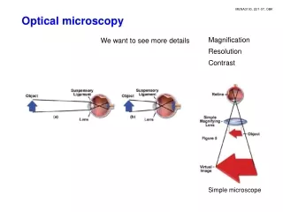
Microscopy:generating, collecting and recording photons from a small source. o
Microscopy:generating, collecting and recording photons from a small source. o
Properties of thin Lenses f f p q 1 1 1 = + p q f q Magnification = p
In a microscope the sample is further from the lens than the focus, so a real, magnified and inverted image is formed. Parallel rays are deflected through the focus; rays through the centre of the lens go straight through, so we can plot where this image will be.
If we move the lens closer to the object the image will get larger and further away - so with a greater 'tube length' - a longer microscope tube - we could get higher magnification with the same lens.
If we move the lens closer to the object the image will get larger and further away - so with a greater 'tube length' - a longer microscope tube - we could get higher magnification with the same lens.
If we move the lens closer to the object the image will get larger and further away - so with a greater 'tube length' - a longer microscope tube - we could get higher magnification with the same lens.
However having the image at different planes is inconvenient and screws up our optical corrections, so we use an objective of shorter focal length to form a more highly magnified image at the same plane. Shorter focal length = higher magnification.
However having the image at different planes is inconvenient and screws up our optical corrections, so we use an objective of shorter focal length to form a more highly magnified image at the same plane. Shorter focal length = higher magnification.
The eyepiece is placed close to the real image formed by the objective; since this is closer to it than its focus, it cannot form a real image. The rays are deflected towards the optic axis but are still diverging from each other.
These rays will therefore appear to an eye, placed beyond the eyepiece, as if they come from a virtual image which is further magnified but the same way up as the real image (and still upside-down relative to the object).
Reflectance Surface reflection and absorption, colour Transmittance Absorption, colour, refractive index Types of microscopy and sources of light. Incandescence Luminescence Fluorescence Excitation & emission
Transmission Optics:Conjugate planes in generalized microscope sample Köhler illumination
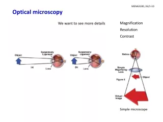
So what makes a “good” image? The most fundamental property of a microscope is its resolution. We are all familiar with the term but sometimes we don't really think about what it means. We may have the vague idea that it means ‘how small a thing we can see’, but this isn't really accurate. Actually we can see things that very tiny indeed but the important thing is the ability to distinguish objects as separate, and that is what resolution means. What determines resolution? One or two?
The first point is that it depends to some extent on your specimen! In transmitted light the illumination makes a big difference to the resolution we get, because the individual points being imaged are not independent of each other. There is partial coherence. In fluorescence, the sample is made up, for imaging purposes, of a collection of luminous points (fluorochrome molecules) each emitting light independently (non coherent).
The image results from the ‘convolution’ of the imaging devise with the object • Transmitted image of a tree on the ground (usually called a shadow). • But the imaging device has an unusual point spread function due to a lunar eclipse
Convolve to find edges • The imaging device is modelled by a matrix of values called a mask or kernal. • It can be used to emphasise different aspects of the image such as edges , for example.
Convolution is a mathematical operation of matrices combining flip, multiply, sum and scan http://www.eas.asu.edu/~karam/2dconvolution/
? Resolution of independent emitting objects A lens forming a magnified image of a fluorochrome molecule - effectively an infinitely small point which emits light. The image at the plane of focus (lower left) is not a point but a disk - called an AIRY DISK - surrounded by a halo, in fact a long series of progressively dimmer haloes. Most of the light is in the disk so we often ignore the haloes. Above and below the focal plane (right) the light fans out in a hollow cone pattern. The complete 3D shape is called the Point Spread Function (PSF).
sinq = 0.25 q sinq = 0.75 What spreads out the light into a disc instead of a point is diffraction of light at the edge of the lens. The diameter of the disk depends on the path differences between rays from opposite edges of the lens. So the size of the disk depends on the size of the lens. To be precise, it depends on the proportion of the total light which the lens can collect - so a small, close lens is equivalent to a larger one further away. It therefore defined by angle - the radius of the disk, r, is given by: r = 0.61 l / sin q where q is the half-angle of acceptance of the lens. q Stage
Rayleigh’s Criterion Rayleigh proposed that we could still tell two Airy disks apart until the first minimum of one was on the centre of the other. So the radius of the Airy disk becomes the definition of resolution. Note that the Airy discs are additive (no interference). r = 0.61 l / sin q
Transmitted light is partially coherent so diffracted waves can interfere • Local domains of filament/arc emit light simultaneously and in phase. • Waves that are split by diffraction maintain this coherence, thus may interfere if brought back together
Transmitted image resolution arises from interference of diffracted waves
nl = d.sinq When a light falls on a small object, or on the edge of a larger one, it is diffracted - scattered in all directions. Each particle will scatter light in all directions. However, if we look at the rays diffracted by each particle at the angle q, we notice something rather interesting. Each will be out of step with its neighbour by exactly one wave-length - in other words, in step with its neighbour. Since these reinforce, the specimen as a whole scatters light strongly in this direction - the others cancel out. Clearly, in the diagram, l / d = sin q. The smaller the spacing, the larger the angle q.
This leads us to Abbe's formula for the resolution of a microscope in transmission mode. The minimum resolved distance (d) is given by: d = l / 2n.sinq What this makes plain is that when we are illuminating a specimen from below, how the light hits the specimen is crucial for good resolution! However wonderful and expensive our objective is, if we don't adjust the condenser properly it is wasted.
In both cases, l and q are what determine resolution The visible spectrum is about 400 to 750 nm, but only about 500-625nm is bright enough to be useful for microscopy. So our scope for improving resolution by varying the wavelength l is limited. The most important factor is to keep sin q as large as possible. If q = 90° then sin q = 1 - this is the theoretical limit and practically inconvenient, but we can get close. Sin q = 0.95 corresponds to q = 72°, which is achievable, and the 5% difference is insignificant. For this case d = l / 2n.sinq works out to 290nm for l = 550nm But to get maximum this resolution, we need contrast.
Increased contrast in transmission microscopy phase DIC • Dark field-condenser angle greater than objective • Phase Contrast Microscopy-cumulative shift of phase over light path • Differential Interference Contrast (DIC)-gradient of refractive index at point of focus
Darkfield The oldest technique for looking at unstained samples using diffracted light. We use a hollow cone of illumination, replacing the condenser diaphragm with a ring-shaped aperture which is large enough for the light to fall outside the acceptance angle q of the objective lens. Light scattered up to an angle of 2q can enter the objective, so we are using its full resolution - but only if the condenser has a higher NA.
Phase Contrast The Dutch physicist Zernike hit upon the idea of making the diffracted rays half a wavelength out of step with the direct rays, so that anything in the specimen which scatters light will appear dark in the final image.
How deep must the groove be? For glass n=1.5, for air n=1. Path difference = depth (t) x difference in refractive indices (1.5 - 1), ie 0.5t. Assuming the refractive index of the cell contents puts the scattered light ~ ¼l behind, we need to slow it by a further ¼l to bring the path difference to ~ ½ l. Taking l = 550nm (the centre of the spectrum), we want the path difference to be ¼l, 550/4 which is 137.5nm. The depth t will therefore be twice this = 275nm.
ray entirely in water – no phase shift • ray goes through edge of cytosol – small phase shift cytosol n = 1.35 water n = 1.3 liposome n = 1.45 • ray goes through more cytosol – larger phase shift • ray goes through edge of liposome – even larger phase shift • ray goes through centre of liposome – largest phase shift
The final result - the more material is present the darker objects appear
Differential Interference Contrast Analyser Introduced by the Polish-French scientist Nomarski. Its basic principle is simple - make each ray of light interfere with another passing through the specimen a very small distance away from it. If the refractive index of the specimen is changing, there will be a path difference between the two rays, if it is uniform there won’t be. The contrast we see in the final image will depend on the local rate of change of refractive index in the specimen - hence the name differential interference contrast. Polariser
both rays in water – no phase difference • one in water, one cytosol – phase difference cytosol n = 1.35 water n = 1.3 liposome n = 1.45 • one sees more cytosol – small phase difference • one in cytosol other in liposome – large phase difference • Both in liposome + cytosol – no phase difference
one in water, one cytosol – phase difference • one sees more cytosol – small phase difference • one in cytosol other in liposome – large phase difference
The final result - a ‘relief’ effect – which is striking but entirely artificial
Differential Interference Contrast Bright Field Dark Field Phase Contrast
Fluorescence Microscopy in theSussex Centre for Advanced Microscopy Roger Phillips Biols 2C9,10,11 Ext 7585 R.G.Phillips@sussex.ac.uk