Download
1 / 22
220 likes | 358 Vues
Enumeration of Irredundant Circuit Structures. Alan Mishchenko Department of EECS UC Berkeley. Overview. Logic synthesis is important and challenging task Boolean decomposition is a way to do logic synthesis Several algorithms - many heuristics Drawbacks

E N D
Enumeration of Irredundant Circuit Structures Alan Mishchenko Department of EECS UC Berkeley
Overview • Logic synthesis is important and challenging task • Boolean decomposition is a way to do logic synthesis • Several algorithms - many heuristics • Drawbacks • Incomplete algorithms - suboptimal results • Computationally expensive algorithms - high runtime • Our goal is to overcome these drawbacks • Perform exhaustive enumeration offline • Use pre-computed results online, to get good Q&R and low runtime • Practical discoveries • The number of unique functions up to 16 inputs is not too high • The number of unique decompositions of a function is not too high 2
Background • And-Inverter Graphs • Structural cuts and mapping • Small practical functions (SPFs) • Boolean decomposition • Disjoint-support decomposition • Non-disjoint-support decomposition • NPN classification • Boolean matching • LUT mapping and LUT structure mapping
d a b a c b c a c b d b c a d AIG Definition and Examples AIG is a Boolean network composed of two-input ANDs and inverters. F(a,b,c,d) = ab + d(ac’+bc) 6 nodes 4 levels F(a,b,c,d) = ac’(b’d’)’ + c(a’d’)’ = ac’(b+d) + bc(a+d) 7 nodes 3 levels
f LUT LUT LUT e a c d b Primary outputs Choice node Primary inputs Mapping in a Nutshell Mapped network AIG f • AIGs reprsent logic functions • A good subject graph for mapping • Technology mapping expresses logic functions to be implemented • Uses a description of a technology • Technology • Primitives with delay, area, etc • Structural mapping • Computes a cover of AIG using primitives of the technology • Cut-based structural mapping • Computes cuts for each AIG node • Associates each cut with a primitive • Selects a cover with a minimum cost • Structural bias • Good mapping cannot be found because of the poor AIG structure • Overcoming structural bias • Need to map over a number of AIG structures (leads to choice nodes) e c d b a
Small Practical Functions • Classifications of Boolean functions • Random functions • Special function classes (symmetric, unate, etc) • Logic synthesis and technology mapping deal with • Functions appearing in the designs • Functions with small support (up to 16 variables) • These functions are called small practical functions (SPFs) • We will concentrate on SPFs and study their properties • In particular, we will ask • How many different SPFs exist? • How many different irredundant logic structures they have?
Ashenhurst-Curtis Decomposition Z(X) = H( G(B), F ), X = B F B (Bound Set) X Z Z F (Free Set) if B F = , this is disjoint-support decomposition (DSD) if B F , this is non-disjoint-support decomposition
00 01 11 10 00 1 1 1 1 01 1 0 1 0 11 0 1 0 1 10 0 0 0 0 Example of Deriving DSD Bound Set={a,b} Incompatibility Graph Free Set ={c,d} G 1 G 2 =2 G 4 G 3 F(a,b,c,d) = (ab+ ab)c+ (ab+ ab)(cd+cd) G(a,b)= ab+ab H(G,c,d) = Gc+ G(cd+cd)
DSD Structure • DSD structure is a tree of nodes derived by applying DSD recursively until remaining nodes are not decomposable • DSD is full if the resulting tree consists of only simple gates (AND/XOR/MUX) • DSD is partial if the resulting tree has non-decomposable nodes (called prime nodes) • DSD does not exist if the tree is composed of one node Full DSD Partial DSD No DSD f f a b a b c d e f c d e a b c d e
F a c d b Computing DSD F(a,b,c,d) = ab + cd • The input is a Boolean function • The output is a DSD structure • The structure is unique up to several normalizations, for example • Placement of inverters • Factoring of multi-input AND/XOR gates • Ordering of fanins of AND/XOR gates • Ordering of data inputs of MUXes • NPN representative of prime nodes • This computation is fast and reliable • Originally implemented with BDDs (Bertacco et al) • In a limited form, re-implemented with truth tables • Detects about 95% of DSDs of cut functions • In 8-LUT mapping, it takes roughly the same time to • to compute structural cuts • to derive their truth tables • to compute DSDs of the truth tables
Pre-computing Non-Disjoint-Support Decompositions • Enumerate bound sets while increasing size • Enumerate shared sets while increasing size • If the bound+shared set is irredundant • Add it to the computed set • Bound+shared set is redundant • If it a variable can be removed and the resulting set is still decomposable • Ex: (abCD) is redundant if (abcD) or (abD) is valid H G a b C D e H H G G e e c a b D a b c D
Example of Non-DS Decomposition:Mapping 4:1 MUX into two 4-LUTs The complete set of support-reducing bound-sets for Boolean function of 4:1 MUX: Set 0 : S = 1 D = 3 C = 5 x=Acd y=xAbef Set 1 : S = 1 D = 3 C = 5 x=Bce y=xaBdf Set 2 : S = 1 D = 3 C = 5 x=Ade y=xAbcf Set 3 : S = 1 D = 3 C = 5 x=Bde y=xaBcf Set 4 : S = 1 D = 3 C = 5 x=Acf y=xAbde Set 5 : S = 1 D = 3 C = 5 x=Bcf y=xaBde Set 6 : S = 1 D = 3 C = 5 x=Bdf y=xaBce Set 7 : S = 1 D = 3 C = 5 x=Aef y=xAbcd Set 8 : S = 1 D = 4 C = 4 x=aBcd y=xBef Set 9 : S = 1 D = 4 C = 4 x=Abce y=xAdf Set 10 : S = 1 D = 4 C = 4 x=Abdf y=xAce Set 11 : S = 1 D = 4 C = 4 x=aBef y=xBcd Set 12 : S = 2 D = 5 C = 4 x=ABcde y=xABf Set 13 : S = 2 D = 5 C = 4 x=ABcdf y=xABe Set 14 : S = 2 D = 5 C = 4 x=ABcef y=xABd Set 15 : S = 2 D = 5 C = 4 x=ABdef y=xABc
H’ f G a b C d e Application to LUT Structure Mapping:Matching 6-input function with LUT structure “44” Case 2 Case 1 Case 3 f f a b c d e f a b c d e a b c d e f f H H H G G G a b c D e f a b C d e a b c D e
Application to Standard Cell Mapping • Enumerate decomposable bound sets • Enumerate decomposition structures for each bound set • Use them as choice nodes • Use choice nodes to improve quality of Boolean matching • Property: When non-disjoint-support decomposition is applied, there are exactly M = 2^((2^k)-1) pairs of different NPN classes of decomposition/composition functions, G and H, where k is the number of shared variables F H G
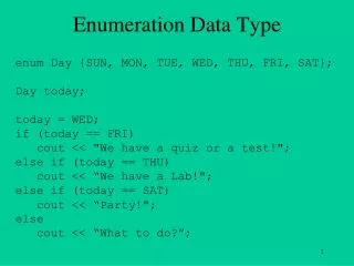
Example of a Typical SPF abc 01> rt 000A115F abc 02> print_dsd –d F = 0505003F(a,b,c,d,e) This 5-variable function has 10 decomposable variable sets: Set 0 : S = 1 D = 3 C = 4 x=abC y=xCde 0 : <cba> 011D{decf} 1 : <c!ba> 110D{decf} Set 1 : S = 1 D = 3 C = 4 x=bCd y=xaCe 0 : !(!d!(cb)) <e(!c!a)!f> 1 : 1C{bdc} 3407{aecf} Set 2 : S = 1 D = 3 C = 4 x=abE y=xcdE 0 : <eab> 0153{cdef} 1 : <e!ab> 5103{cdef} Set 3 : S = 1 D = 3 C = 4 x=acE y=xbdE 0 : !(!c!(ea)) 01F3{bdef} 1 : 1C{ace} F103{bdef} Set 4 : S = 1 D = 3 C = 4 x=bcE y=xadE 0 : (c!(!e!b)) (!f<e!a!d>) 1 : 38{bce} 5003{adef} Set 5 : S = 1 D = 3 C = 4 x=bCe y=xaCd 0 : !(!e!(cb)) <f(!c!a)!d> 1 : 1C{bec} 3503{adcf} Set 6 : S = 1 D = 3 C = 4 x=adE y=xbcE 0 : <ead> (!f!(c!(!e!b))) 1 : <e!ad> 3007{bcef} Set 7 : S = 1 D = 4 C = 3 x=abcE y=xdE 0 : FAC0{abce} (!f!(!ed)) 1 : 05C0{abce} C1{def} Set 8 : S = 1 D = 4 C = 3 x=aCde y=xbC 0 : <e!(!c!a)d> (!f!(cb)) 1 : 03AC{adec} 43{bcf} Set 9 : S = 1 D = 4 C = 3 x=bcdE y=xaE 0 : CCF8{bcde} (!f!(ea)) 1 : 33F8{bcde} 43{aef} abc 01> rt 000A115F abc 02> pk Truth table: 000a115f d e \ a b c 0 0 0 0 1 1 1 1 0 0 1 1 1 1 0 0 0 1 1 0 0 1 1 0 +---+---+---+---+---+---+---+---+ 00 | 1 | 1 | 1 | 1 | 1 | | | 1 | +---+---+---+---+---+---+---+---+ 01 | | | | | 1 | | | 1 | +---+---+---+---+---+---+---+---+ 11 | | | | | | | | | +---+---+---+---+---+---+---+---+ 10 | 1 | 1 | | | | | | | +---+---+---+---+---+---+---+---+ NOTATIONS: !a is complementation NOT(a) (ab) is AND(a,b) [ab] is XOR(a,b) <abc> is MUX(a, b, c) = ab + !ac <truth_table>{abc} is PRIME node
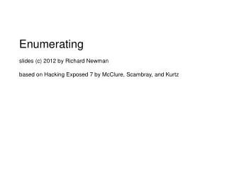
Statistics of DSD Manager This DSD manager was created using cut enumeration applied to *all* MCNC, ISCAS, and ITC benchmarks circuits (the total of about 835K AIG nodes). This involved computing 16 priority 12-input cuts at each node. Binary file “pub12_16.dsd” has size 177 MB. Gzipped archive has size 42 MB. Reading it into ABC takes 3 sec. abc 01> pub12_16.dsd; dsd_ps Total number of objects = 3567880 Externally used objects = 3060774 Non-DSD objects (max =12) = 479945 Non-DSD structures = 3220044 Prime objects = 1405170 Memory used for objects = 100.04 MB. Memory used for functions = 238.01 MB. Memory used for hash table = 40.83 MB. Memory used for bound sets = 79.98 MB. Memory used for array = 27.22 MB. 0 : All = 1 Non = 0 ( 0.00 %) 1 : All = 1 Non = 0 ( 0.00 %) 2 : All = 2 Non = 0 ( 0.00 %) 3 : All = 10 Non = 0 ( 0.00 %) 4 : All = 229 Non = 0 ( 0.00 %) 5 : All = 3823 Non = 0 ( 0.00 %) 6 : All = 22273 Non = 0 ( 0.00 %) 7 : All = 77959 Non = 0 ( 0.00 %) 8 : All = 200088 Non = 0 ( 0.00 %) 9 : All = 396307 Non = 0 ( 0.00 %) 10 : All = 661620 Non = 0 ( 0.00 %) 11 : All = 972333 Non = 0 ( 0.00 %) 12 : All = 1233234 Non = 0 ( 0.00 %) All : All = 3567880 Non = 0 ( 0.00 %) abc 01> time elapse: 3.00 seconds, total: 3.00 seconds
Typical DSD Structures NOTATIONS: !a is complementation NOT(a) (ab) is AND(a,b) [ab] is XOR(a,b) <abc> is MUX(a, b, c) = ab + !ac <truth_table>{abc} is a PRIME node with hexadecimal <truth_table>
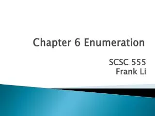
Support-Reducing Decompositions • For each support size (S) of NPN classes of non-DSD-decomposable functions • the columns are ranges of counts of irredundant decompositions • the entries are percentages of functions in each range • - the last two columns are the maximum and average decomposition counts
LUT Structure Mapping • LUT: LUT count • Level: LUT level count • Time, s: Runtime, in seconds • The last two columns: • with online DSD computations • with offline DSD computations (based on pre-computed data)
LUT Level Minimization 6-LUT mapping: Standard mapping into 6-LUTs LUTB: DSD-based LUT balancing proposed in this work SOPB+LUTB: SOP balancing followed by LUT balancing (ICCAD’11) LMS+LUTB: Lazy Man’s Logic Synthesis followed by LUT balancing (ICCAD’12)
Conclusions • Introduced Boolean decomposition • Proposed exhaustive enumeration of decomposable sets • Discussed applications to Boolean matching • Experimented with benchmarks to find a 3x speedup in LUT structure mapping • Future work will focus on • Improving implementation • Extending to standard cells • Use in technology-independent synthesis
Abstract • A new approach to Boolean decomposition and matching is proposed. It uses enumeration of all support-reducing decompositions of Boolean functions up to 16 inputs. The approach is implemented in a new framework that compactly stores multiple circuit structures. The method makes use of pre-computations performed offline, before the framework is started by the calling application. As a result, the runtime of the online computations is substantially reduced. For example, matching Boolean functions against an interconnected LUT structure during technology mapping is reduced to the extent that it no longer dominates the runtime of the mapper. Experimental results indicate that this work has promising applications in CAD tools for both FPGAs and standard cells.