Download
1 / 36
360 likes | 495 Vues
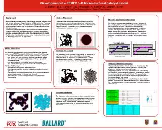
Development of a 3-d Cubic crystal calorimeter for space. Oscar Adriani INFN and University of Florence Paris , April 25 th , 2013. 1 particle / m 2 ×second. 1 particle / m 2 ×year . 1 particle / km 2 ×year . High energy nuclei “ Knee” structure around ~ PeV

E N D
Development of a 3-d Cubic crystal calorimeter for space Oscar Adriani INFN and University of Florence Paris, April 25th, 2013
1 particle / m2×second 1 particle / m2×year 1 particle / km2×year • High energy nuclei • “Knee” structure around ~ PeV • Upper energy of galactic accelerators (?) • Energy-dependent composition • Structures in the GeV – TeV region recently discovered for p and He • Composition at the knee may differ substantially from that at TeV • Spectral measurements in the knee region up to now are only indirect • Ground-based atmospheric shower detectors • High uncertainties • A direct spectral measurement in the PeV region requires great acceptance (few m2sr) and good energy resolution for hadrons (at least 40%) Some of the Cosmic-Ray ‘mysteries’ • High energy Electrons+Positrons • Currently available measurements show some degree of disagreement in the 100 GeV – 1 TeVregion • Cutoff in the TeV region? • Direct measurements require excellent energy resolution (~%), a high e/p rejection power (> 105) and large acceptance above 1 TeV
Our proposal for an ‘optimal’ CR detector • A 3-D, deep, homogeneous and isotropic calorimeter can achieve these design requirements: • depth and homogeneity to achieve energy resolution • isotropy (3-D) to accept particles from all directions and increase GF • Proposal: a cubic calorimeter made of small cubic sensitive elements • can accept events from 5 sides (mechanical support on bottom side) → GF * 5 • segmentation in every direction gives e/p rejection power by means of topological shower analysis • cubic, small (~Moliéreradius) scintillating crystals for homogeneity • gaps between crystals increase GF and can be used for signal readout • small degradation of energy resolution • must fulfill mass&power budget of a space experiment • modularity allows for easy resizing of the detector design depending on the available mass&power
Additional details…. • Exercise made on the assumption that the detector’s only weight is ~ 1600 kg • Mechanical support is not included in the weight estimation • The optimal material is CsI(Tl) Density: 4.51 g/cm3 X0: 1.85 cm Moliere radius: 3.5 cm lI: 37 cm Light yield: 54.000 ph/MeV tdecay: 1.3 ms lmax: 560 nm • Simulation and prototype beam tests used to characterize the detector (* one Moliere radius) (** GF for only one face)
The readout sensors and the front-end chip • Minimum 2 Photo Diodes are necessary on each crystal to cover the whole huge dynamic range 1 MIP107MIPS • Large Area ExcelitasVTH2090 9.2 x 9.2 mm2 for small signals • Small area 0.5 x 0.5 mm2 for large signals • Front-End electronics: a big challenge! • The CASIS chip, developed in Italy by INFN-Trieste, is very well suited for this purpose • IEEE TRANSACTIONS ON NUCLEAR SCIENCE, VOL. 57, NO. 5, OCTOBER 2010 • 16 channels CSA+CDS • Automatic switching btw low and high gain mode • 2.8 mW/channel • 3.103 e- noise for 100 pF input capacitance • 53 pC maximum input charge
MC simulations • Fluka-based MC simulation • Scintillating crystals • Photodiodes • Energy deposits in the photodiodes due to ionization are taken into account • Carbon fiber support structure (filling the 3mm gap) • Isotropic generation on the top surface • Results are valid also for other sides • Simulated particles: • Electrons: 100 GeV → 1 TeV • Protons: 100 GeV → 100 TeV • about 102 – 105 events per energy value • Geometry factor, light collection and quantum efficiency of PD are taken into account • Requirements on shower containment (fiducial volume, length of reconstructed track, minimum energy deposit) • Nominal GF: (0.78*0.78*π)*5*εm2sr= 9.55*ε m2sr
Electrons Electrons 100 – 1000 GeV Selection efficiency: ε ~ 36% GFeff ~ 3.4 m2sr RMS~2% Crystals only Crystals + photodiodes Non-gaussian tails due to leakages and to energy losses in carbon fiber material (Measured Energy – Real Energy) / Real Energy Ionization effect on PD: 1.7%
100 – 1000 GeV 1 TeV 32% 35% (Measured Energy – Real Energy) / Real Energy (Measured Energy – Real Energy) / Real Energy 100 TeV 10 TeV 39% 40% (Measured Energy – Real Energy) / Real Energy (Measured Energy – Real Energy) / Real Energy Protons Energy resolution (correction for leakage by looking at the shower starting point) Selection efficiencies: ε0.1-1TeV ~ 35% ε1TeV~ 41% ε10TeV~ 47% GFeff0.1-1TeV ~ 3.3 m2sr Gfeff1TeV~ 3.9 m2sr Gfeff10TeV~ 4.5 m2sr Proton rejection factor with simple topological cuts: 2.105-5.105 up to 10 TeV
The prototypes and the test beams • Two prototypes have been built at INFN Florence, with the help of INFN Trieste, INFN Pisa and University of Siena. • A small, so called “pre-prototype”, made of 4 layers with 3 crystals each • 12 CsI(Tl) crystals, 2.5x2.5x2.5 cm3 • A bigger, properly called “prototype”, made of 14 layers with 9 crystals each • 126 CsI(Tl) crystals, 3.6x3.6x3.6 cm3 • Both devices have been tested at CERN SPS (pre-prototype in October 2012 and prototype in January-February 2013)
The prototype 14 Layers 9x9 crystals in each layer 126 Crystals in total 126 Photo Diodes 50.4 cm of CsI(Tl) 27 X0 1.44 lI
For deuterium: S/N ~ 14 2H 4He A glance at prototype's TB data Please note: we can use the data from a precise silicon Z measuring system located in front of the prototype to have an exact identification of the nucleus charge!!!! SPS H8 Ion Beam: Z/A = 1/2, 12.8 GV/c and 30 GV/c
A glance at prototype's TB data N Please remind that this is a calorimeter!!!! Not a Z measuring device!!!! C B H: Z=1 <ADC>=330 He: Z=2 <ADC>=1300 Li: Z=3 <ADC>=3000 Be: Z=4 <ADC>=5300 B: Z=5 <ADC>=8250 C: Z=6 <ADC>=12000 N Z=7 <ADC>=16000 Be Li He
Total energydeposit VS shower-startinglayer 30GV Preliminary Z=2 Z=1 Maximalcontainmentwhenstarting-layer == 2
Averagelongitudinalprofile (1.44 lI) 30GV/c Preliminary Z=2 Z=1 (Startinglayer == 2)
Energy deposit for various nuclei Charge is selected with the placed-in-front tracking system Good Linearity even with the large area PD! Preliminary
How to improve the calorimeter performances? • We could try to see the Cherenkov light produced in the crystals by the electromagnetic component of the shower • Improvement of the e/p rejection factor • Improvement of the hadronic energy resolution (DREAM project) Possibility to use the timing information to discriminate btw scintillation (slow) and Cherenkov (fast) component Cherenkov light is a small fraction of the scintillaton light, compatible with the direct energy release in the PD….
Some ideas for the Cherenkov light • Use of SiPM to detect Cherenkov light • Discrimination btw Fast Cherenkov light and Slow Scintillation light possible with dedicated fast sampling electronics • Use of SiPM highly sensitive in the UV region • Use of ‘UV transmitting’ filters on the SiPM face • to block the largely dominant scintillation light • Possible use of ≥3 SiPM for each crystal on orthogonal faces • to have a good uniformity in the response for particles hitting the different calorimeter’s faces • R&D is under way…. More news at the end of the year!
Conclusion • An homogeneous, isotropic calorimeter looks to be an optimal tool for the direct detection of High Energy CR • The status of the project is quite advanced: • Simulation • Prototypes • Test beams • Next steps: • R&D on the Cherenkov light during 2013 • Low energy electron test beam in INFN Frascati in autumn 2013 for Cherenkov light studies • Possibly enlarge the prototype’s dimensions • R&D for the Calibration system of every crystal is certainly necessary to optimize the whole calorimeter’s performances
What we can reach with this calorimeter? Electrons ~ knee Assumptions: • 10 years exposure • No direct closeby sources for electrons • Polygonato model for protons/nuclei
Shower starting point resolution <ΔX> = 1.15 cm
Protons Energy estimation Shower length can be used to reconstruct the correct energy 100 – 1000 GeV Red points: profile histogram Fitted with logarithmic function Signal / Energy Shower Length (cm)
Proton 1 TeV Signal / Energy Shower Length (cm)
Energy resolution ΔE = 17%
Proton rejectionfactor Montecarlo study of proton contamination using CALORIMETER INFORMATIONS ONLY • PARTICLES propagation & detector responsesimulated with FLUKA • Geometricalcuts for showercontainment • Cutsbased on longitudinal and lateraldevelopment l1 10TeV • 155.000 protonssimulatedat 1 tev : only 1 survive the cuts • The corresponding electron efficiencyis 37% and almostconstant with energyabove 500gev • Mc study of energydependence of selectionefficiencyand calo energydistribution of misreconstructedevents 1TeV LONGITUDINAL protons electrons LATERAL LatRMS4
Proton rejectionfactor Contamination : 0,5% at 1TeV 2% at 4 TeV Protons in acceptance(9,55m2sr)/dE vela E3dN/dE(GeV2 ,s-1 ) An upper limit 90% CL is obtained using a factor X 3,89 Electrons in acceptance(9,55m2sr)/dE Electrons detected/dEcal Protons detected as electrons /dEcal E(GeV) = = 0,5 x 10⁶ X Electron Eff. ~ 2 x 10⁵
Noise WITHand WITHOUTCN subtraction CN evaluatedwithoutdisconnectedchannels
Signal in the central cube in High Gain (Blu) and Low Gain (Red)
Response uniformity of the crystals ~14% Uniformity
Pre-prototype test Muon beam MIP muons are clearly visible S/N ~ 16.5
Matching region btw high and low gain Not perfect commutation of CSIS btw high and low gain regions
Energy resolution (veryrough) Preliminary Preliminary 37% (fit) 58% (fit) Z=2 Z=1 30 GV/c Starting-layer ==2 No cuts and no corrections on the incident position
Expected resolution from simulation Particle hitting the center of the crystals 31% 24%
Dual readout –> BGO: scintillation + Cherenkov Hardware compensation Filter: 250 ÷ 400 nm for Cherenkow light >450 nm for Scintillator light Even better for CsI(Tl) since the scintillation light emission is very slow