Download
1 / 47
971 likes | 2.84k Vues
Orthographic Projection. Objectives. List the six principal views of projection Sketch the top, front and right-side views of an object with normal, inclined, and oblique surfaces. Objectives (cont.). Understand which views show depth in a drawing that shows top, front, and right-side views

E N D
Objectives • List the six principal views of projection • Sketch the top, front and right-side views of an object with normal, inclined, and oblique surfaces
Objectives (cont.) • Understand which views show depth in a drawing that shows top, front, and right-side views • Know the meaning of normal, inclined, and oblique surfaces
Objectives (cont.) • Know which dimensions transfer between top, front, and right-side views • Transfer the depth between the top and right-side views • Label points where surfaces intersect
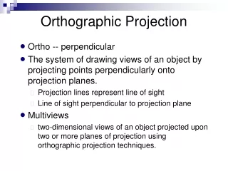
Views of Objects • Drawings are two-dimensional representations of objects that allow you to record sizes and shapes precisely • To provide a complete and clear description, the views must be systematically arranged • The system of views is called multiview projection
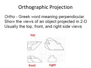
The Six Standard Views • Any object can be viewed from six mutually perpendicular views
The Six Standard Views • These views are called principal views and are arranged in a standard way
The Six Standard Views • The top, front, and bottom views align vertically • The rear, left-side, front, and right-side views align horizontally • To draw a view out of place is a serious error
Principal Dimensions • The three principal dimensions of an object are: • Width • Height • Depth
Principal Dimensions • Any principal view shows two of the three principal dimensions • Height is shown in the rear, left-side, front, and right side • Width is shown in the rear, top, front, and bottom • Depth is shown in the left-side, top, right-side, and bottom views
Projection Method • Frontal plane – the plane upon which the frontal view is projected • Horizontal plane – the plane upon which the top view is projected • Profile plane – the plane upon which the side view is projected
The Glass Box • One way to understand the standard arrangement of views on a sheet of paper is to envision the object in a glass box • The outside observer would see six standard views of the object through the sides of this imaginary glass box
Transferring Depth Dimensions • The depth dimensions in the top and side views must correspond • You may find it convenient to use dividers, a ruler, or a 45-degree miter line to project dimensions
Necessary Views • A sketch or drawing should only contain the views needed to clearly and completely describe the object • Choose the views that have the fewest hidden lines and show essential contours or shapes most clearly • Complicated objects may require more than three views • Some objects only need one or two views
Orientation of the Front View • The front view should: • Show a large surface of the part parallel to the front viewing plane • Show the shape of the object clearly • Show the object in a usual, stable, or operating positions
Orientation of the Front View • When possible, a machine part is drawn in the orientation it occupies in the assembly • Usually screws, bolts, shafts, tubes, and other elongated parts are drawn in a horizontal position
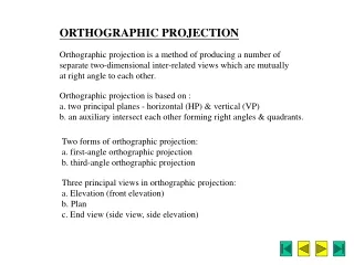
First- and Third-Angle Projection • There are two main systems used for projecting and unfolding the views: • Third-angle projection which is used in the United States, Canada and some other countries • First-angle projection which is primarily used in Europe and Asia • You should understand both methods
Hidden Lines • An advantage of orthographic views is that each view shows the object all the way through as if it were transparent • Thick dark lines represent visible features • Dashed lines represent features that would be hidden behind other surfaces • When possible, choose views that show features with visible lines
Centerlines • The centerline is used to: • Show the axis of symmetry of a feature or part • Indicate a path of motion • Show the location for bolt circles or other circular patterns • The centerline pattern is composed of three dashes, one long dash on each end with a short dash in the middle
Precedence of Lines • When lines coincide on a drawing the rules of precedence are: • Visible lines always take precedence over hidden or centerlines • Hidden lines take precedence over centerlines
Visualization • Even those with experience can’t always look at a multiview sketch and instantly visualize the object represented • You will learn to interpret lines in a logical way in order to visualize the object as a whole
Views of Surfaces • A plane surface that is perpendicular to a plane of projection appears on edge as a straight line • If a plane is parallel to the plane of projection, it appears true size • If a plane is angled to the plane of projection, it appears foreshortened
Views of Surfaces • A plane surface always projects either on edge or as a surface in any view • It can appear foreshortened, smaller than actual size, but it can never appear larger than its true size in any view
Normal Surfaces • A normal surface is parallel to a plane of projection
Inclined Surfaces • An inclined surface is perpendicular to one plane of projection but inclined to adjacent planes
Oblique Surfaces • An oblique surface is tipped to all principal planes of projection and does not appear true size in any standard view
Edges • The intersection of two plane surfaces of an object produces an edge which shows as a straight line in a drawing • If an edge is perpendicular to a plane of projection it appears as a point, otherwise it appears as a line
Parallel Edges • When edges are parallel to one another on an object, they will appear as parallel lines in every view unless they align one behind the other
Angles • If an angle is in a normal plane, it will show true size on the plane of projection to which it is parallel • If an angle is in an inclined plane, it may be projected either larger or smaller than the true angle depending on its position
Interpreting Lines • A straight, visible, or hidden line in a sketch has three possible meanings: • An edge between two surfaces • The edge view of a surface • The limiting element of a curved surface • Since no shading is used on orthographic views, you must examine all views to determine a line’s meaning
Similar Shapes of Surfaces • If a flat surface is viewed from several different positions, each view will show the same number of sides and vertices and same characteristic shape whenever it appears as a surface • This consistency of shapes is useful in analyzing views
Interpreting Views • One method of interpreting sketches is to reverse the mental process used in projecting them • Each view provides certain definite information about the shape of the object and all are necessary to visualize it completely