Download
1 / 11
110 likes | 128 Vues
TCAD Simulation for SOI Pixel Detector. October 31, 2007 IEEE-NSS, Honolulu, Hawaii, USA Hirokazu Hayashi, Hirotaka Komatsubara (Oki Elec. Ind. Co.), Yasuo Arai, Masashi Hazumi (KEK), Yuji Saegusa (TIT) for the SOIPIX group. SOIPIX collaborators.

E N D
TCAD Simulation forSOI Pixel Detector October 31, 2007 IEEE-NSS, Honolulu, Hawaii, USA Hirokazu Hayashi, Hirotaka Komatsubara (Oki Elec. Ind. Co.), Yasuo Arai, Masashi Hazumi (KEK), Yuji Saegusa (TIT) for the SOIPIX group
SOIPIX collaborators KEK Detector Technology Project : [SOIPIX Group] Y. Arai*, M. Hazumi, Y. Ikegami, T. Kohriki, O. Tajima, S. Terada, T. Tsuboyama, Y. Unno, H. Ushiroda,H. IkedaA,K. HaraB, H. MiyakeB, H. IshinoC, Y. SaegusaC, T. KawasakiD, E. MartinE, G. VarnerE, H. TajimaF, K. FukudaG, H. HayashiG, H. KomatsubaraG, J. IdaG , M. OhnoG KEK、JAXAA, U. TsukubaB, TITC,Niigata U.D, U. HawaiiE, SLACF, OKI Elec. Ind. Co.G (*)—contact person M. Hazumi (KEK)
TCAD Topics covered in this talk Process simulation • Back gate effect • Circuit-sensor crosstalk • Implantation parameters • Guard ring design • Pixel layout Device simulation Overview TCAD = Technology CAD • ENEXSS (Environment for NExt Simulation System) • Developed by Selete (Semiconductor Leading Edge Technologies) ( http://www.selete.co.jp/?lang=EN ) • Full 3D process/device simulation ! • Commercially available from TCAD-International ( http://www.tcad-international.com/ENEXSS_e.html ) Real LSI Manufacturing Specifications Virtual Fast Deeper understanding Function design Logic design Process data Circuit design Device data Layout design ~3mon. Characterization Mask fabrication Prototyping M. Hazumi (KEK) Device production
ENEXSS TCAD Threshold voltage (V) Back Gate ENEXSS -20 -10 0 +10 +20 Back bias (V) VB (V) Back gate effect Substrate voltage acts as Back Gate, and changes transistor threshold. TCAD Measurement M. Hazumi (KEK)
Back gate effect:mitigation with p+ implants MPW06 NMOS distance (D) (40 – 2 mm) BOX (200nm) (5 mm wide P+, 1 x 1020 cm-3) Bulk: N- (~700ohm cm, 6 x 1012 cm-3) 350mm p+ implant (0V) for I/O buffer ENEXSS D Measurement (10MHz clock) Back bias = 40V Out In M. Hazumi (KEK) Back bias Much improved !
Circuit-sensor crosstalk Signals in the circuitry very close to the sensor may inject noise to the sensor. ENEXSS Input OK for charge-integrated device. Need some care for other cases M. Hazumi (KEK)
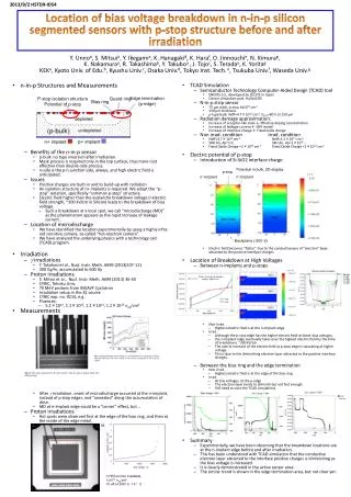
Implantation parameters Find the best ion and beam energy to achieve the highest breakdown voltage (vital important for full depletion) • “Deeper” implantation mitigates impact ionization (II) and results in a higher breakdown voltage. • ~20% improvement expected by doing both. Example 1) Ion #2 Ion #1 2mm Vbreak = +88.5V = +102.4V Example 2) ENEXSS M. Hazumi (KEK)
Test structure (strip sensor) MPW06 Standard New Measurement ~20% improvement observed M. Hazumi (KEK)
SOI pixel detector ... ... Pixels VSS Ring I/O 100000 Bias Ring edge Bias Ring Guard Ring 80000 1 guard ring (MPW06) 2 guard rings (next submission) 60000 E [V/cm] 40000 20000 Bias Guard Guard d [um] 40 30 0 10 20 Guard ring design Better guard ring design also helpful to improve breakdown voltage. ENEXSS MPW06 1 guard + 1bias MPW06 2 guards + 1bias 20V at the back side An additional guard ring is effective to reduce the electric field concentration. M. Hazumi (KEK)
20 10 0 15 5 ① 4 16 ② 3 17 ③ A B Pixel layout For digital readout, charge sharing curve at the cell boundary should be as steep as possible. cell A cell B Note that in our design there are 4 p+ implants in one cell connected in the readout. MIP-like charge injection with TCAD for the 3 layouts shown below ENEXSS +:① +:② +:③ x [mm] Narrower gap b/w two cells (③) slightly better. x 2 M. Hazumi (KEK)
Summary • Back gate effect largely mitigated with additional p+ implants near the circuitry. • Circuit-sensor crosstalk is not an issue for digital pixel readout with charge integration. • Higher breakdown voltage with improved implantation parameters (~20% achieved) • Additional guard ring can reduce the electric field by factor ~2. • Implantation gap b/w two cells should be minimized (present design seems close to the best) • Good prospects for thinned fully-depleted SOI pixel ! M. Hazumi (KEK)