Download
1 / 10

E N D
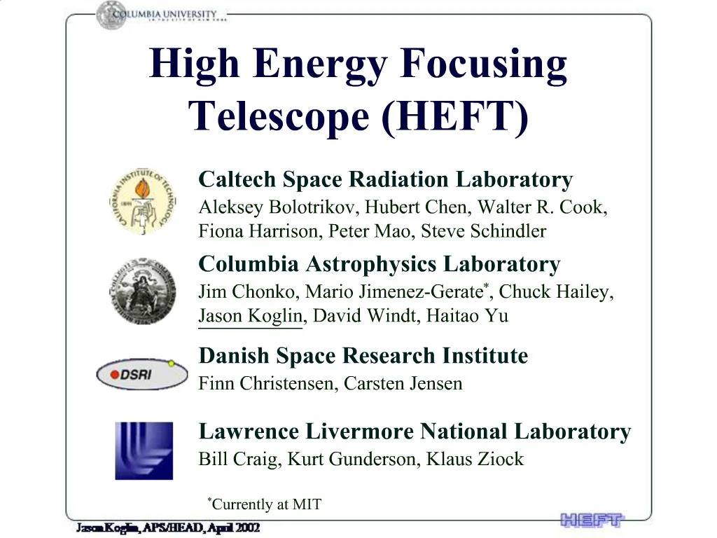
1. High Energy Focusing Telescope (HEFT) The High Energy Focusing Telescope (HEFT) is a balloon-borne experiment employing focusing optics in the hard X-ray band (20 - 100 keV) for sensitive observations of astrophysical sources. HEFT is a close collaboration of four institutes: Caltech, Columbia where I�m a postdoc with Chuck Hailey, DSRI in Copenhagen, and Livermore. The High Energy Focusing Telescope (HEFT) is a balloon-borne experiment employing focusing optics in the hard X-ray band (20 - 100 keV) for sensitive observations of astrophysical sources. HEFT is a close collaboration of four institutes: Caltech, Columbia where I�m a postdoc with Chuck Hailey, DSRI in Copenhagen, and Livermore.
2. HEFT Science We intend to not only be among the first to fly focusing hard X-ray optics, but we also plan to use them in an aggressive scientific research program to investigate the following astrophysical sources with a resolution and sensitivity far surpassing that previously available using the previous generation of coded aperture and collimated optics. The primary scientific objectives include imaging and spectroscopy of 44Ti emission in young supernova remnants, sensitive hard X-ray observations of obscured Active Galactic Nuclei, and spectroscopic observations of accreting high-magnetic field pulsars. The galactic center is also a rich region to observe high energy phenomena such as compact objects in outburst and quiescence.
Priority Key Projects
Young SNR:
Map 44Ti (68 & 78 keV) in Cas-A in 1-2� bins
1-2� maps of nonthermal continuum to E ~> 40 keV
AGN:
Measure high-energy continuum in Chandra/XMM hard sample
Survey IR/optical sample (75% of Ginga 2 � 10 keV sample detectable to 80 keV)
Accreting High-Magnetic Neutron Stars
Resolve complex features in Her X-1 and other bright sources
Measure cyclotron lines @ 60 keV for Lpulsar ~> 4 x 1034 erg/s
Galactic Center (Sgr A*)
Observe compact objects in outburst/quiesence
Improve mass accretion rate limit by 100x for central black hole
Key to pictures
Supernova:
The red, green, and blue regions in this Chandra X-ray image of the supernova remnant Cassiopeia A show where the intensity of low, medium, and high energy X rays, respectively, is greatest. The red material on the left outer edge is enriched in iron, whereas the bright greenish white region on the lower left is enriched in silicon and sulfur. In the blue region on the right edge, low and medium energy X rays have been filtered out by a cloud of dust and gas in the remnant.
(Image and Text Credit: NASA/CXC/SAO/Rutgers/J.Hughes, found at http://imagine.gsfc.nasa.gov/docs/features/exhibit/cgro_snr.html)
AGN:
Active galaxies produce tremendous amounts of energy from an extremely small region in the center, a region usually called the nucleus of the galaxy. The process behind this is not very clear, but astronomers think that these active galaxies all contain a supermassive black hole in their centers, which swallows stars and gas clouds and converts gravitational energy to radiation. Often active galaxies show bright, narrow "jets" of emission from their nuclei. One famous example of this is the "quasar" (quasi-stellar radio object) 3C273. This Chandra image shows the active nucleus of the galaxy (in the upper left) as a bright source of X-rays, and shows a narrow jet of X-rays pointing from the nucleus and stretching for hundreds of thousands of lightyears from the quasar.
(Credit: NASA/CXC/SAO/H. Marshall et al., with image and description found at http://heasarc.gsfc.nasa.gov/docs/objects/heapow/archive/active_galaxies/chandra_3c273_jet.html)
X-ray Pulsar:
These images of X-rays from the Crab nebula are selected from a 5 hour exposure taken with the Einstein HRI. The length of the exposure is one full pulsar cycle, and clearly shows the pulsar growing to its brightest primary pulse, fading and then brightening again to its secondary pulse after which it fades completely at the end of the cycle.
(Credit: F. R. Harnden (CfA) , with image and description found at http://heasarc.gsfc.nasa.gov/docs/objects/snrs/crab_pulses.html)
Galactic Center:
GRANAT was a Russian astronomical observatory satellite dedicated to X-ray and gamma ray astronomy. GRANAT operated from 1989 to 1998 and was a collaborative observatory which included instruments from a number of European countries. The SIGMA telescope on GRANAT was a coded mask instrument provided by France. Coded-mask telescopes are a bit unusual in that they don't have imaging optics (like a lens or mirror) to produce images. Coded-mask telescopes consist of a thick patterned mask in front of the detector; from the variation of the intensity of the light falling on the detector, and from the known mask pattern, an image of the observed object can be reconstructed. A SIGMA image of the galactic center is shown above. This image is one of the deepest high energy images of the galactic center ever obtained.
We intend to not only be among the first to fly focusing hard X-ray optics, but we also plan to use them in an aggressive scientific research program to investigate the following astrophysical sources with a resolution and sensitivity far surpassing that previously available using the previous generation of coded aperture and collimated optics. The primary scientific objectives include imaging and spectroscopy of 44Ti emission in young supernova remnants, sensitive hard X-ray observations of obscured Active Galactic Nuclei, and spectroscopic observations of accreting high-magnetic field pulsars. The galactic center is also a rich region to observe high energy phenomena such as compact objects in outburst and quiescence.
Priority Key Projects
Young SNR:
Map 44Ti (68 & 78 keV) in Cas-A in 1-2� bins
1-2� maps of nonthermal continuum to E ~> 40 keV
AGN:
Measure high-energy continuum in Chandra/XMM hard sample
Survey IR/optical sample (75% of Ginga 2 � 10 keV sample detectable to 80 keV)
Accreting High-Magnetic Neutron Stars
Resolve complex features in Her X-1 and other bright sources
Measure cyclotron lines @ 60 keV for Lpulsar ~> 4 x 1034 erg/s
Galactic Center (Sgr A*)
Observe compact objects in outburst/quiesence
Improve mass accretion rate limit by 100x for central black hole
Key to pictures
Supernova:
The red, green, and blue regions in this Chandra X-ray image of the supernova remnant Cassiopeia A show where the intensity of low, medium, and high energy X rays, respectively, is greatest. The red material on the left outer edge is enriched in iron, whereas the bright greenish white region on the lower left is enriched in silicon and sulfur. In the blue region on the right edge, low and medium energy X rays have been filtered out by a cloud of dust and gas in the remnant.
(Image and Text Credit: NASA/CXC/SAO/Rutgers/J.Hughes, found at http://imagine.gsfc.nasa.gov/docs/features/exhibit/cgro_snr.html)
AGN:
Active galaxies produce tremendous amounts of energy from an extremely small region in the center, a region usually called the nucleus of the galaxy. The process behind this is not very clear, but astronomers think that these active galaxies all contain a supermassive black hole in their centers, which swallows stars and gas clouds and converts gravitational energy to radiation. Often active galaxies show bright, narrow "jets" of emission from their nuclei. One famous example of this is the "quasar" (quasi-stellar radio object) 3C273. This Chandra image shows the active nucleus of the galaxy (in the upper left) as a bright source of X-rays, and shows a narrow jet of X-rays pointing from the nucleus and stretching for hundreds of thousands of lightyears from the quasar.
(Credit: NASA/CXC/SAO/H. Marshall et al., with image and description found at http://heasarc.gsfc.nasa.gov/docs/objects/heapow/archive/active_galaxies/chandra_3c273_jet.html)
X-ray Pulsar:
These images of X-rays from the Crab nebula are selected from a 5 hour exposure taken with the Einstein HRI. The length of the exposure is one full pulsar cycle, and clearly shows the pulsar growing to its brightest primary pulse, fading and then brightening again to its secondary pulse after which it fades completely at the end of the cycle.
(Credit: F. R. Harnden (CfA) , with image and description found at http://heasarc.gsfc.nasa.gov/docs/objects/snrs/crab_pulses.html)
Galactic Center:
GRANAT was a Russian astronomical observatory satellite dedicated to X-ray and gamma ray astronomy. GRANAT operated from 1989 to 1998 and was a collaborative observatory which included instruments from a number of European countries. The SIGMA telescope on GRANAT was a coded mask instrument provided by France. Coded-mask telescopes are a bit unusual in that they don't have imaging optics (like a lens or mirror) to produce images. Coded-mask telescopes consist of a thick patterned mask in front of the detector; from the variation of the intensity of the light falling on the detector, and from the known mask pattern, an image of the observed object can be reconstructed. A SIGMA image of the galactic center is shown above. This image is one of the deepest high energy images of the galactic center ever obtained.
3. Supernova Just to quickly key on one of the primary objectives involving Young Supernova Remnants. 44Ti is synthesized near the mass cut � the boundary between the innermost ejecta and the material that falls back to form the collapsed remnant. The production and ejection of 44Ti is sensitive to the explosion mechanism and ejecta dynamics. Thus, we want to map 44Ti (68 & 78 keV) in Cas-A in 1-2� bins.
The 44Ti COMPTEL measurements of Cas A at 1.157 MeV with 2.2 degree resolution are shown here in (a). Next in (b) is a much more detailed simulation of a HEFT observation at 68/78 keV, 1� resolution, 80 ksec LDB observation. The simulation assumes a (clearly resolved) clumpy, axisymmetric explosion. The ROSAT contour plot is shown for comparison. Also shown are the spectra of the two hemispheres in (c), assuming that the top one was ejected away from the observer at �2000 km/s, and the bottom one toward the observer at +2000 km/s � moderate velocities for this SNR. Each hemisphere was also assumed to have an internal velocity dispersion of 1000 km/s.
Just to quickly key on one of the primary objectives involving Young Supernova Remnants. 44Ti is synthesized near the mass cut � the boundary between the innermost ejecta and the material that falls back to form the collapsed remnant. The production and ejection of 44Ti is sensitive to the explosion mechanism and ejecta dynamics. Thus, we want to map 44Ti (68 & 78 keV) in Cas-A in 1-2� bins.
The 44Ti COMPTEL measurements of Cas A at 1.157 MeV with 2.2 degree resolution are shown here in (a). Next in (b) is a much more detailed simulation of a HEFT observation at 68/78 keV, 1� resolution, 80 ksec LDB observation. The simulation assumes a (clearly resolved) clumpy, axisymmetric explosion. The ROSAT contour plot is shown for comparison. Also shown are the spectra of the two hemispheres in (c), assuming that the top one was ejected away from the observer at �2000 km/s, and the bottom one toward the observer at +2000 km/s � moderate velocities for this SNR. Each hemisphere was also assumed to have an internal velocity dispersion of 1000 km/s.
4. Instrument Overview I don�t have much time for details, but want to emphasize that we are using focusing optics illustrated by the cartoon on the right and a prototype telescope we built on the left.
HEFT consists of an array of co-aligned conical-approximation Wolter I mirror assemblies. The 300 mm thin nested-shell mirrors are separated from the focal plane detectors by 6 meters. W/Si depth-graded multilayer coatings provide high-energy reflectivity at reasonable graze angles, with response extending to 70 keV (other coatings will later be used to get up to 100 keV). CdZnTe pixel detectors will provide 1 keV energy resolution. The design calls for 14 optic modules to provide an effective area of 250 cm2, an angular resolution of 1 arcminute Half-Power Diameter (HPD) and a field of view (FOV) of 17 arcminutes. Up to fourteen telescope modules will be mounted on a precision pointing platform with 20� pointing stability. So what is this thing going to look like?I don�t have much time for details, but want to emphasize that we are using focusing optics illustrated by the cartoon on the right and a prototype telescope we built on the left.
HEFT consists of an array of co-aligned conical-approximation Wolter I mirror assemblies. The 300 mm thin nested-shell mirrors are separated from the focal plane detectors by 6 meters. W/Si depth-graded multilayer coatings provide high-energy reflectivity at reasonable graze angles, with response extending to 70 keV (other coatings will later be used to get up to 100 keV). CdZnTe pixel detectors will provide 1 keV energy resolution. The design calls for 14 optic modules to provide an effective area of 250 cm2, an angular resolution of 1 arcminute Half-Power Diameter (HPD) and a field of view (FOV) of 17 arcminutes. Up to fourteen telescope modules will be mounted on a precision pointing platform with 20� pointing stability. So what is this thing going to look like?
5. HEFT Flight Assembly In preparation for a spring 2003 flight, the instrument components are being prepared for full integration on the HEFT balloon gondola. Here you see the gondola in the center surrounded by more detailed pictures of the major components. Here you can see the star tracker, control components and electronics provided by Livermore. Five CdZnTe detectors with their flight shields, built by Caltech, have been tested and appear to be working well, and the pressurized Kevlar dome in which they will be housed is ready. And the flight optic modules provided by Columbia are in the process of being assembled by Colorado Precision Products in Boulder, CO. Since the optics are what I am most intimately involved, I will concentrate on them for the rest of this talk.In preparation for a spring 2003 flight, the instrument components are being prepared for full integration on the HEFT balloon gondola. Here you see the gondola in the center surrounded by more detailed pictures of the major components. Here you can see the star tracker, control components and electronics provided by Livermore. Five CdZnTe detectors with their flight shields, built by Caltech, have been tested and appear to be working well, and the pressurized Kevlar dome in which they will be housed is ready. And the flight optic modules provided by Columbia are in the process of being assembled by Colorado Precision Products in Boulder, CO. Since the optics are what I am most intimately involved, I will concentrate on them for the rest of this talk.
6. Multilayer Coated Glass Optics A major accomplishment of the HEFT program has been the successful development of thermally-formed glass optics with performance exceeding the HEFT requirements. Because of the large effective area requirements of HEFT, we are driven to obtain high angular resolution at low cost per unit area. This is possible using thin glass originally developed for flat panel displays that is smooth and flat on all relevant length scales.
Our approach is to thermally form these micro-sheets using standard quartz mandrels and commercially available ovens. We begin by placing a glass micro-sheet on the mandrel inside of the oven. As the oven is heated to the appropriate forming temperature, the glass begins to form under the influence of gravity. Just before the glass touches the mandrel surface, the forming process is terminated by lowering the oven temperature. In this way, near net shaped optic substrates are produced without perturbing the excellent initial X-ray properties of the glass micro-sheet, even without the aid of highly polished and very expensive mandrels.
The simplicity of this process allows for high performance optics to be mass produced in a university laboratory environment on a tightly constrained budget. HEFT glass is produced in 8 ovens operated by 1.5 FTE technicians at Columbia University. With these resources we can produce one layer of flight grade HEFT optics substrates per day. It is easy to envision scaling these efforts for much larger satellite projects.
Multilayer coatings are required to enhance the reflectivity with a broad energy acceptance. A multilayer structure is a stack of thin layers (typically several hundred layers) of alternating materials designed so that the small reflections from each layer add in phase. Depth-graded multilayers vary the bi-layer thickness so that different layers are optimized to reflect different wavelengths, providing broadband response. For W/Si multilayers, the absorption edge of W limits the effective operating energy range below 70 keV. To extend the bandpass to 100 keV requires the use of NiV/Si coatings on the inner (the low graze angle/high energy) shells. The substrates are coated at DSRI in the coating chamber shown here on the left at a rate almost twice that at which we can produce substrates. And this here is what a coated shell looks like.
A major accomplishment of the HEFT program has been the successful development of thermally-formed glass optics with performance exceeding the HEFT requirements. Because of the large effective area requirements of HEFT, we are driven to obtain high angular resolution at low cost per unit area. This is possible using thin glass originally developed for flat panel displays that is smooth and flat on all relevant length scales.
Our approach is to thermally form these micro-sheets using standard quartz mandrels and commercially available ovens. We begin by placing a glass micro-sheet on the mandrel inside of the oven. As the oven is heated to the appropriate forming temperature, the glass begins to form under the influence of gravity. Just before the glass touches the mandrel surface, the forming process is terminated by lowering the oven temperature. In this way, near net shaped optic substrates are produced without perturbing the excellent initial X-ray properties of the glass micro-sheet, even without the aid of highly polished and very expensive mandrels.
The simplicity of this process allows for high performance optics to be mass produced in a university laboratory environment on a tightly constrained budget. HEFT glass is produced in 8 ovens operated by 1.5 FTE technicians at Columbia University. With these resources we can produce one layer of flight grade HEFT optics substrates per day. It is easy to envision scaling these efforts for much larger satellite projects.
Multilayer coatings are required to enhance the reflectivity with a broad energy acceptance. A multilayer structure is a stack of thin layers (typically several hundred layers) of alternating materials designed so that the small reflections from each layer add in phase. Depth-graded multilayers vary the bi-layer thickness so that different layers are optimized to reflect different wavelengths, providing broadband response. For W/Si multilayers, the absorption edge of W limits the effective operating energy range below 70 keV. To extend the bandpass to 100 keV requires the use of NiV/Si coatings on the inner (the low graze angle/high energy) shells. The substrates are coated at DSRI in the coating chamber shown here on the left at a rate almost twice that at which we can produce substrates. And this here is what a coated shell looks like.
7. Telescope Assembly Method The mounting process we have developed for the glass is unique. Graphite spacers are epoxied into place on a lightweight mandrel and precisely machined so that their surface corresponds to the exact figure required for the 1st layer of glass to be laid down. Next, epoxy is placed on the spacers and the glass is then appropriately positioned and compressed onto the spacers. After epoxy cure, another layer of spacers is placed on top of the 1st layer of glass. These spacers are then machined and the next layer of glass is epoxied into place.
The process is repeated for as many layers as are required (72 in the case of HEFT). A key point of this approach is that, because the spacers for each glass layer are machined with respect to the optic axis and not the last layer of glass, there is never any stack up error in tolerances during the fabrication of the telescope. The assembly machine itself contributes less than 8� to the overall error budget. The conformance of the glass directly on top of these spacers is spectacular as is shown here for the glass on top of three spacers constraining one shell segment where I plot the surface height as a function of the axial length along the spacers.
Down here to the right is a picture of an actual flight module being assembled at CPPI. We have a fully operational production environment there, and we are moving full speed ahead assembling optics with a dedicated tech doing all the work.
All it takes is one person in order to lay down a complete layer of glass each day. As I said before, we are cranking out glass at Columbia at this rate too and are coating the glass at DSRI at an even faster rate, and we are doing all of this using only limited manpower.
Because major missions of the future will require enormous areas to be rapidly assembled, it is essential to develop techniques like this that use limited infrastructure and low cost raw materials, and also do not rely on labor intensive processes.
The mounting process we have developed for the glass is unique. Graphite spacers are epoxied into place on a lightweight mandrel and precisely machined so that their surface corresponds to the exact figure required for the 1st layer of glass to be laid down. Next, epoxy is placed on the spacers and the glass is then appropriately positioned and compressed onto the spacers. After epoxy cure, another layer of spacers is placed on top of the 1st layer of glass. These spacers are then machined and the next layer of glass is epoxied into place.
The process is repeated for as many layers as are required (72 in the case of HEFT). A key point of this approach is that, because the spacers for each glass layer are machined with respect to the optic axis and not the last layer of glass, there is never any stack up error in tolerances during the fabrication of the telescope. The assembly machine itself contributes less than 8� to the overall error budget. The conformance of the glass directly on top of these spacers is spectacular as is shown here for the glass on top of three spacers constraining one shell segment where I plot the surface height as a function of the axial length along the spacers.
Down here to the right is a picture of an actual flight module being assembled at CPPI. We have a fully operational production environment there, and we are moving full speed ahead assembling optics with a dedicated tech doing all the work.
All it takes is one person in order to lay down a complete layer of glass each day. As I said before, we are cranking out glass at Columbia at this rate too and are coating the glass at DSRI at an even faster rate, and we are doing all of this using only limited manpower.
Because major missions of the future will require enormous areas to be rapidly assembled, it is essential to develop techniques like this that use limited infrastructure and low cost raw materials, and also do not rely on labor intensive processes.
8. Metrology Comparison Now I want to go over the performance of a full three layer test optic that was characterized using three independent metrology methods yielding consistent results.
In the first method, essentially zero force LVDT surface measurements were performed on each shell as the optic was being assembled. From the complete surface maps generated from this data, a simulated image was generated using a ray trace code. This surface topology yields a lot of information on the individual glass shells that is extremely useful in understanding the over-constraint mounting process as well as accurately predicting the optic performance.
In the second method, 8 keV X-ray pencil beam scans are performed at DSRI. This gives a composite two-bounce performance of the upper and lower shells together at multiple azimuthal positions using X-rays very close to the 20-100 keV design energy of the telescope. Further, the X-ray background is extremely low, and with the precision fixturing shown here, there are only minimal systematic uncertainties associated co-adding the individual scans.
In the third method, the optic is fully illuminated with parallel UV radiation at the University of Colorado�s CASA lab. I should note that we are very grateful to CASA for hosting us as guests at their excellent long-beam UV facility. Using this approximate UV point source, the full true image generated by the optic is directly measured with an MCP detector. While this provides for no detailed information on the individual optic components, it unambiguously provides a �what you see is what you get� result for the image requiring no intermediate data analysis steps.
Each of these methods have different strengths, and together, they provide for a very clear, complete, and self consistent understanding of optic performance.
Now I want to go over the performance of a full three layer test optic that was characterized using three independent metrology methods yielding consistent results.
In the first method, essentially zero force LVDT surface measurements were performed on each shell as the optic was being assembled. From the complete surface maps generated from this data, a simulated image was generated using a ray trace code. This surface topology yields a lot of information on the individual glass shells that is extremely useful in understanding the over-constraint mounting process as well as accurately predicting the optic performance.
In the second method, 8 keV X-ray pencil beam scans are performed at DSRI. This gives a composite two-bounce performance of the upper and lower shells together at multiple azimuthal positions using X-rays very close to the 20-100 keV design energy of the telescope. Further, the X-ray background is extremely low, and with the precision fixturing shown here, there are only minimal systematic uncertainties associated co-adding the individual scans.
In the third method, the optic is fully illuminated with parallel UV radiation at the University of Colorado�s CASA lab. I should note that we are very grateful to CASA for hosting us as guests at their excellent long-beam UV facility. Using this approximate UV point source, the full true image generated by the optic is directly measured with an MCP detector. While this provides for no detailed information on the individual optic components, it unambiguously provides a �what you see is what you get� result for the image requiring no intermediate data analysis steps.
Each of these methods have different strengths, and together, they provide for a very clear, complete, and self consistent understanding of optic performance.
9. Laser Scanner vs. LVDT We also have a laser scanning apparatus at Columbia that provides full surface slope characterization of cylindrical shells (both freestanding and mounted in surrogate fixtures that approximate the mounting process). From this data I can generate complete surface maps of the entire substrates. It is instructive to both model and compare actual data of freestanding and mounted glass. Laser Scanner measurements of the freestanding shells and LVDT metrology of the mounted shells are available for almost all pieces of glass mounted on previous prototypes as well as the current flight telescopes. I show as an example one characteristic shell. On the top left is the raw laser data from a freestanding shell where I�ve plotted the surface height residuals from cylindrical vs. the optical axis and azimuthal (i.e., curved axis). LVDT metrology on the same mounted shell is shown next in the top left. You can see that we take out a significant twist in the glass via the over-constrained mounting process. But more importantly, we are taking this nominally cylindrical shell slumped in one of our 24 cylindrical mandrels and forcing it to accurately conform to one of almost 150 unique conic shapes required to build a heft optic. Being able to do this simplifies the production of glass and avoids the large costs associated with buying mandrels (even low cost mandrels) for each shell. We constrain the overall shape with ease, we remove twists in the glass, but the axial performance of the glass remains largely unaffected. This is evident from the plots below which show the same glass surface, but with the phase errors (i.e. the relative slope and height offsets in each of the several axial scans) removed. Comparison of the free standing and mounted glass in this way shows that the axial scans indeed remain largely unaffected by the mounting process except near the spacers.
This sort of analysis gives us hope that we can accurately predict the performance of glass pieces before mounting them and in this way we can establish solid acceptance criteria to assure we achieve the desired optics performance. Further, with detailed finite element analysis (FEA) we should be able to more accurately determine what the appropriate number and configuration of spacers, the type of substrates, etc� we should use without the expense of building actual prototype optics. We have some really powerful tools that can be used in developing very high performance optics for future satellite missions.
We also have a laser scanning apparatus at Columbia that provides full surface slope characterization of cylindrical shells (both freestanding and mounted in surrogate fixtures that approximate the mounting process). From this data I can generate complete surface maps of the entire substrates. It is instructive to both model and compare actual data of freestanding and mounted glass. Laser Scanner measurements of the freestanding shells and LVDT metrology of the mounted shells are available for almost all pieces of glass mounted on previous prototypes as well as the current flight telescopes. I show as an example one characteristic shell. On the top left is the raw laser data from a freestanding shell where I�ve plotted the surface height residuals from cylindrical vs. the optical axis and azimuthal (i.e., curved axis). LVDT metrology on the same mounted shell is shown next in the top left. You can see that we take out a significant twist in the glass via the over-constrained mounting process. But more importantly, we are taking this nominally cylindrical shell slumped in one of our 24 cylindrical mandrels and forcing it to accurately conform to one of almost 150 unique conic shapes required to build a heft optic. Being able to do this simplifies the production of glass and avoids the large costs associated with buying mandrels (even low cost mandrels) for each shell. We constrain the overall shape with ease, we remove twists in the glass, but the axial performance of the glass remains largely unaffected. This is evident from the plots below which show the same glass surface, but with the phase errors (i.e. the relative slope and height offsets in each of the several axial scans) removed. Comparison of the free standing and mounted glass in this way shows that the axial scans indeed remain largely unaffected by the mounting process except near the spacers.
This sort of analysis gives us hope that we can accurately predict the performance of glass pieces before mounting them and in this way we can establish solid acceptance criteria to assure we achieve the desired optics performance. Further, with detailed finite element analysis (FEA) we should be able to more accurately determine what the appropriate number and configuration of spacers, the type of substrates, etc� we should use without the expense of building actual prototype optics. We have some really powerful tools that can be used in developing very high performance optics for future satellite missions.
10. Optics Development Now, we are building one arcminute optics for HEFT as has been demonstrated by a HEFT prototype optic with relatively large statistics, which is significantly better then the 100-150� of Astro-E and ASCA (Serlemitsos 1998, 2002) and ~150� of SODART for soft X-rays.
We have also been actively pursuing developing even higher performance optics that can be used for future satellite missions such as Con-X HXT as well as smaller midex and explorer class satellites such as a Nuclear Line Telescope which would require multilayers that extend reflectivities up to 170 keV and for which I don�t have time to talk about, but you could talk with David Windt who is an expert on this from Columbia about this later.
I want to show a couple examples of our development work. First, we have built a prototype with 5 cm segments (not 2 m which would be very impressive indeed!) which has a combined 39� HPD performance. I show the LVDT surface metrology data for one of the shells in this prototype with 30� HPD (two-bounce) performance in the plot here below of the fraction of energy enclosed in a circle with diameter corresponding to the performance shown on the x axis. Second, we have build a 51� prototype using 200 mm thin glass instead of the 300 mm thick glass used for HEFT. This shows that we can get just as good of performance while saving on weight and increasing the ability to pack more effective area into a telescope. Below shows one shell as an example from this prototype with a very excellent performance of 31�.Now, we are building one arcminute optics for HEFT as has been demonstrated by a HEFT prototype optic with relatively large statistics, which is significantly better then the 100-150� of Astro-E and ASCA (Serlemitsos 1998, 2002) and ~150� of SODART for soft X-rays.
We have also been actively pursuing developing even higher performance optics that can be used for future satellite missions such as Con-X HXT as well as smaller midex and explorer class satellites such as a Nuclear Line Telescope which would require multilayers that extend reflectivities up to 170 keV and for which I don�t have time to talk about, but you could talk with David Windt who is an expert on this from Columbia about this later.
I want to show a couple examples of our development work. First, we have built a prototype with 5 cm segments (not 2 m which would be very impressive indeed!) which has a combined 39� HPD performance. I show the LVDT surface metrology data for one of the shells in this prototype with 30� HPD (two-bounce) performance in the plot here below of the fraction of energy enclosed in a circle with diameter corresponding to the performance shown on the x axis. Second, we have build a 51� prototype using 200 mm thin glass instead of the 300 mm thick glass used for HEFT. This shows that we can get just as good of performance while saving on weight and increasing the ability to pack more effective area into a telescope. Below shows one shell as an example from this prototype with a very excellent performance of 31�.
11. Achievements Achievements so far:
We have utilized surrogate mounts to simulate the mounting process in our lab at Columbia for R&D purposes (much less expensive than building prototypes at CPPI) and used our laser metrology capabilities
We have demonstrated that we have less than 8� error in our assembly machine at CPPI
We have demonstrated consistency of X-ray, UV & LVDT metrology methods which provides us a lot of tools to understand very quickly what is taking place in our process and where we at in terms of performance.
We can correlate free-standing (Laser) and mounted glass (LVDT)
We have built 1.0� HEFT prototype optic using 300 mm thick glass substrates
We have built a 51� optic using 200 mm thick glass, which by the way, meets Con-X HXT weight and performance requirements, something that I don�t think anyone else has really demonstrated yet.
We have built a 39� optic using short glass segments.
We are by no means content to stop where we are at and have the following plans:
Perform in-depth data analysis in addition to using FEA experts at Livermore to more fully understand our process and perhaps its ultimate limits.
Improve thermal glass slumping process and characterization
Develop new and improved multilayer coatings up to 170 keV (D. Windt)
Collaborate with GSFC on mounting Epoxy Replicated Thermally Formed Glass (W. Zhang). We are really excited about the prospect of using our mounting technique for these substrates that start with our idea of forming glass but take it a step further to get extremely high performance through epoxy replication off of a high precision mandrel.
We have lots of ideas for next generation substrates: mandrel-less forming of glass, graphite thermo-vacuum forming, VELCRO an idea of Mario Jimenez-Gerate a former student at Columbia now at MIT, and very thin Si wafers in place of glass the we are starting to look at, which are flexible enough to be bent and require no forming at all.
Improve assembly machine to ~3� with true Wolter-I parabolic/ hyperbolic geometry
Achievements so far:
We have utilized surrogate mounts to simulate the mounting process in our lab at Columbia for R&D purposes (much less expensive than building prototypes at CPPI) and used our laser metrology capabilities
We have demonstrated that we have less than 8� error in our assembly machine at CPPI
We have demonstrated consistency of X-ray, UV & LVDT metrology methods which provides us a lot of tools to understand very quickly what is taking place in our process and where we at in terms of performance.
We can correlate free-standing (Laser) and mounted glass (LVDT)
We have built 1.0� HEFT prototype optic using 300 mm thick glass substrates
We have built a 51� optic using 200 mm thick glass, which by the way, meets Con-X HXT weight and performance requirements, something that I don�t think anyone else has really demonstrated yet.
We have built a 39� optic using short glass segments.
We are by no means content to stop where we are at and have the following plans:
Perform in-depth data analysis in addition to using FEA experts at Livermore to more fully understand our process and perhaps its ultimate limits.
Improve thermal glass slumping process and characterization
Develop new and improved multilayer coatings up to 170 keV (D. Windt)
Collaborate with GSFC on mounting Epoxy Replicated Thermally Formed Glass (W. Zhang). We are really excited about the prospect of using our mounting technique for these substrates that start with our idea of forming glass but take it a step further to get extremely high performance through epoxy replication off of a high precision mandrel.
We have lots of ideas for next generation substrates: mandrel-less forming of glass, graphite thermo-vacuum forming, VELCRO an idea of Mario Jimenez-Gerate a former student at Columbia now at MIT, and very thin Si wafers in place of glass the we are starting to look at, which are flexible enough to be bent and require no forming at all.
Improve assembly machine to ~3� with true Wolter-I parabolic/ hyperbolic geometry