Download
1 / 43
440 likes | 633 Vues
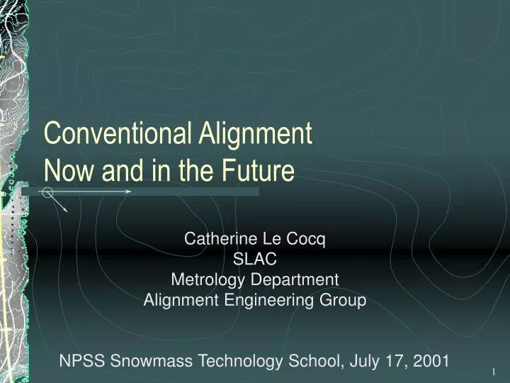
Conventional Alignment Now and in the Future. Catherine Le Cocq SLAC Metrology Department Alignment Engineering Group. NPSS Snowmass Technology School, July 17, 2001. Presentation Outline. Surface Network Transfer between Surface and Tunnel Networks Tunnel Network Components Alignment.

E N D
Conventional AlignmentNow and in the Future Catherine Le Cocq SLAC Metrology Department Alignment Engineering Group NPSS Snowmass Technology School, July 17, 2001
Presentation Outline • Surface Network • Transfer between Surface and Tunnel Networks • Tunnel Network • Components Alignment Catherine Le Cocq SLAC Alignment Engineering Group
Alignment Strategies Conventional Alignment Special Alignment Systems Wire Systems Hydrostatic Level Systems Straightness Measurement Systems Beam Based Alignment Robert Ruland, SLAC
Typical Equipment and its Resolution Theodolite .3” Gyro-Theod. 1” EDM 100µm/.1km GPS 4mm/30km Level .2mm/km Plummet .1mm/100m L.Tracker 15µm/10m Conventional AlignmentEquipment Robert Ruland, SLAC
Conventional AlignmentSurface Network Purpose: Establishing a global network of pillars and benchmarks to control the positioning, orientation and scale of the entire accelerator. • Instruments Used: • Theodolites + EDMs + Levels • GPS + Levels Catherine Le Cocq SLAC Alignment Engineering Group
GPS Geodetic Receivers Manufacturers Allen Osborne Ass. Ashtech Dassault Sercel NP Geotronics Leica Magellan Novatel Topcon S.A.R.L. Trimble Trimble 4000 SSi model Catherine Le Cocq SLAC Alignment Engineering Group
BAHN/GPSOBS European Space Agency (ESA) Bernese Software Astronomische Instituts Universität Bern (AIUB), Switzerland CGPS22 Geological Survey of Canada, (GSC), Canada DIROP University of New Brunswick (UNB), Canada EPOS.P.V3 GeoForschungsZentrum (GFZ), Germany GAMIT/GLOBK Massachusetts Institute of Technology (MIT), USA GAS University of Nottingham, Great Britain GEODYN Goddard Space Flight Center (NASA/GSFC), USA GEOSAT Norwegian Defense Research Establishment (NDRE), Norway GIPSY/OASIS Jet Propulsion Laboratory (JPL), USA MSOP National Aerospace Laboratory, Japan OMNIS Naval Surface Warfare Center, (NSWC), USA PAGE3 National Geodetic Survey (NGS), USA TEXGAP/MSODP University of Texas Center for Space Research, (UTCSR), USA GPS Research Software Source: IGN/ENSG/LAREG France Catherine Le Cocq SLAC Alignment Engineering Group
One Global Datum: the CTRS Z IRP International Reference Pole Geocenter IRS International Reference Meridian Y X CTRS = Conventional Terrestrial Reference System Catherine Le Cocq SLAC Alignment Engineering Group
How to get to the CTRS? Catherine Le Cocq SLAC Alignment Engineering Group
Solution for the Surface Network:Work within a realization of ITRS • By using postfit GPS orbits expressed in ITRS coordinates. These are freely distributed by the International GPS Service (IGS). • By transforming any other control points into the same reference frame. Catherine Le Cocq SLAC Alignment Engineering Group
GPS and GLONASS Catherine Le Cocq SLAC Alignment Engineering Group
lB lA B HAB A Now, what about adding leveling observations? Na 3000 Spirit Leveling HAB = lA – lB Catherine Le Cocq SLAC Alignment Engineering Group
Different Height Systems With g measured (Earth) gravity, normal (Model) gravity Catherine Le Cocq SLAC Alignment Engineering Group
P H earth’s surface h Po N geiod Q Qo ellipsoid Pizzetti’s Projection Catherine Le Cocq SLAC Alignment Engineering Group
How to compute geoid undulations? 1. Directly 2. Bruns 3. Stokes 4. Helmert Catherine Le Cocq SLAC Alignment Engineering Group
NGM+ Ng + NT NGM+ Ng NGM Ellipsoid Three components in the geoid NGM = long wavelength calculated from a geopotential model Ng = medium wavelengthcomputed with Stokes NT= terrain correction Catherine Le Cocq SLAC Alignment Engineering Group
Local Geoid • Start with a good regional geoid. In the US: G99SS published by NGS as a 1 by 1 arc minute grid. • Add gravity measurements and generate finer terrain model. • Incorporate geoid heights derived from GPS / leveling data. Catherine Le Cocq SLAC Alignment Engineering Group
What about tidal effects? • Tide-free: All effects of the sun and moon removed. • Zero: The permanent direct effects of the sun and moon are removed but the indirect component related to the elastic deformation of the earth is retained. • Mean: No permanent tidal effects are removed. Catherine Le Cocq SLAC Alignment Engineering Group
The datum of the surface network is transferred into the tunnel through penetrations or shafts. Equipment: Optical Plummet, EDM, Level Conventional AlignmentTransfer between Surface and Tunnel Networks Robert Ruland, SLAC
Plummet Catherine Le Cocq SLAC Alignment Engineering Group
Conventional AlignmentTunnel Network Purpose: Establishing a network of combined wall and floor monuments to be used in the placement and monitoring of the components . • Instruments Used: • Theodolites, EDMs, Laser Trackers, Total Stations • Levels • Gyro-theodolites Catherine Le Cocq SLAC Alignment Engineering Group
Theodolites: TC2002 and T3000 Catherine Le Cocq SLAC Alignment Engineering Group
ME5000 EDM Catherine Le Cocq SLAC Alignment Engineering Group
Gyro-theodolite: GYROMAT 2000 Catherine Le Cocq SLAC Alignment Engineering Group
Conventional AlignmentComponents Alignment Purpose: Laying out, installing, mapping and monitoring the accelerator components both locally and globally to the given tolerances. • Instruments Used: • Total Stations • Laser trackers + Levels Catherine Le Cocq SLAC Alignment Engineering Group
SMX Laser Tracker Catherine Le Cocq SLAC Alignment Engineering Group
Tracker vs. HP Interferometer Catherine Le Cocq SLAC Alignment Engineering Group
Coordinate Systems Machine Lattice – Site System: XS 1. Assign location: 2. Choose orientation: Surface Network – Global System: XC Catherine Le Cocq SLAC Alignment Engineering Group
Conventional alignment capabilitiesvs.NLC linac alignment requirements Conventional Alignment cannot meet NLC main linac short wavelength quadrupole tolerance requirements Robert Ruland, SLAC
50 m wall monument 50 m 5 km penetration 1 m 50 m floor monument gyro 0.5 km Simulated Layout Old forced centering approach using 2D connected network approach: - Horizontal angles .3 mgon - Distances 100 m - Azimuths .5 mgon Catherine Le Cocq SLAC Alignment Engineering Group
SLAC/DESY operational range: ± 1 mm resolution 100 nm bi-axial KEK operational range: ± 2.5 mm resolution 2.5 µm Single axis CERN operational range: ± 2.5 mm resolution 1 µm Single or two axis Special Alignment SystemsWire Systems Robert Ruland, SLAC
ESRF/Fogale Nanotech HLS water fully automated, tested res. 1µm, acc. ± 10 µm SLAC FFTB System mercury based capacitive res. 0.5µm, acc. ±2 µm prototype Special Alignment SystemsHydrostatic Level Systems Robert Ruland, SLAC
Conventional Alignment + Wire + HSL vs.NLC linac alignment requirements Robert Ruland, SLAC
Special Alignment SystemsStraightness System with Movable Target Autocollimation (optical / electro-optical) • Taylor Hobson, DA 400 • Möller-Wedel Elcomat 2000, ±5 µm/10 m Interferometric Measurements • HP, Zygo, ±5 µm/10 m Light Intensity Comparison • LMS200, ±10 µm/10m Fixed Beam, movable detector • Positioning System LRP, ±10 µm/10m Robert Ruland, SLAC
Autocollimation ELCOMAT 2000 Resolution 0.05” Accuracy +/- 0.25” Maximum Distance 25m Catherine Le Cocq SLAC Alignment Engineering Group
Interferometric Measurement Catherine Le Cocq SLAC Alignment Engineering Group
Special Alignment SystemsStraightness Systems with Stationary Target Fixed Beam/fxd. Detector Laser System • Retractable target (CERN, Quesnel), ±20 µm/50 m • Fixed transparent target (Max-Plank-Institute/CERN, Munich), max. 6 targets, ±50 µm/50 m Diffraction Optics System • Fresnel Lens (SLAC), ±50 µm/3000 m • Poisson Sphere (LNL, Griffith), ±5 µm/50 m Robert Ruland, SLAC
RTRSSRapid Tunnel Reference Survey System TESLA Alignment Working Group chaired by J. Prenting, DESY W. Schwarz, Weimar University R. Ruland, SLAC Catherine Le Cocq SLAC Alignment Engineering Group
RTRSS Development Stages • Initial Investigation FFTB stretched wire • First Concept Rigid 5 m long bar • Actual Design Train 22.5 m long with 6 measurement cars Catherine Le Cocq SLAC Alignment Engineering Group
RTRSS Measurement Train Prenting, 2001 Catherine Le Cocq SLAC Alignment Engineering Group
RTRSS Individual Measurement Car Prenting, 2001 Prenting, 2001 Catherine Le Cocq SLAC Alignment Engineering Group
Surface Network GPS + Levels Transfer Network Plummet, wire, etc Tunnel Network RTRSS Components Placement Laser Trackers Proposed Strategy Catherine Le Cocq SLAC Alignment Engineering Group
Present and Future Studies • Instrumentation RTRSS development at DESY • Modeling Micro geoid Adjustment simulation • Information System GIS Catherine Le Cocq SLAC Alignment Engineering Group